In industrial automation, for data communication between mobile locomotives and the central control room, the wired communication method is inconvenient due to the dragging communication cable; the wireless communication method causes a high bit error rate due to the harsh industrial site environment. Induction wireless data communication (Data Transmission by Induction Radio) [1] uses the electromagnetic induction between the coded cable (also called the induction bus) and the induction antenna to exchange information. Because there is and is only a wireless communication distance of 5-20cm, it is both It can ensure the flexibility of locomotive movement and ensure the reliability of communication quality, and can simultaneously detect the position of the moving locomotive during the communication process [2].
Industrial field electrical equipment, especially the frequency conversion speed control device on a mobile locomotive, can produce strong harmonics that are the same or similar to the inductive wireless data communication carrier frequency. This kind of co-frequency interference noise cannot be attenuated by a band-pass filter. If effective measures are not taken at the input end to suppress it, the bit error rate of inductive wireless data communication will be greatly increased, and it may even fail to work properly. Baosteel's phase 1 coke oven three-power renovation used equipment imported from Japan. In actual work, "there is a phenomenon of frequent interruption of induced bus communication. The analyzed reasons are random strong interference and antenna detection distortion [3]". Therefore, inductive wireless technology abandons inductive wireless data communication and only uses inductive wireless position detection technology in some practical applications.
In order to suppress interference in inductive wireless data communications, experts and scholars in the same field have done a lot of useful research. Literature [4] proposes an inductive wireless differential receiving antenna device; Literature [5] proposes a method of dual receiving antennas and a single transmission line. The co-channel interference suppression technology for inductive wireless data communication [6] of "dual transmission lines and single receiving antennas crossing at the same distance" proposed in this article can effectively suppress co-channel interference noise, improve the signal-to-noise ratio, and is suitable for ground position detection.
2 Basic principles of inductive wireless data communication
In order to analyze the principle of co-channel interference suppression technology to improve the signal-to-noise ratio in inductive wireless data communication, first a brief analysis and introduction of the basic principles of inductive wireless data communication are given.
2.1 Coding cable and induction antenna
The appearance of the coding cable is flat, and there are several pairs of transmission lines inside, which cross at different locations according to certain coding rules. The coding cable is installed along the moving locomotive track and the beginning is connected to the central control room.
The induction antenna contains two sets of coils, one as a transmitting antenna and one as a receiving antenna, which are packaged in a plastic box, commonly known as an antenna box. The antenna box is installed on the mobile locomotive and connected to the control cabinet on the locomotive. The antenna box moves with the locomotive and always maintains a distance of 5-20cm from the coding cable. see picture 1.
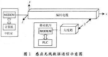
When the antenna box and the coding cable are close to each other, each pair of transmission lines in the coding cable and the coil in the antenna box induce each other, so a short-distance wireless communication channel is formed between the antenna box and the coding cable.
2.2 Amplitude and phase analysis of induced signals
Figure 2 is a schematic diagram of the transmission line L and the antenna coil tiling. In Figure 2, the width of the antenna is equal to the spacing between two intersections of the communication transmission lines in the coding cable, both of which are W, W=2r.
Definition: The center point of the antenna coil is the position of the antenna coil; the area between the two intersections of the transmission line L is called the K area of the transmission line L (K = Ⅰ, Ⅱ, Ⅲ,...). The antenna coil position x deviates from the center line distance of the K area where x is located. for d.
Using the antenna coil as the transmitting coil, the induced electromotive force e generated by the communication transmission line is analyzed. According to the theory of electromagnetic induction, when the current i=Imsinωt passes through the antenna coil, the induced electromotive force generated by the transmission line e=di/dt. Here, the mutual inductance coefficient M is a function of the position of the antenna coil (x, y, z). Assume that the antenna coil When moving in the x direction, y and z do not change, then:
e=f(x)ωImcosωt
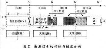
Due to a crossover, the induced electromotive force eI generated in area I of the transmission line is opposite in phase to the induced electromotive force eII generated in area II. If the phase of eI is used as the standard, let ![]() :, then when n is an even number, the induced electromotive force e generated by the transmission line has the same phase as eI; when n is an odd number, the phases of e and eI are opposite, and the phase coefficient is (-1)n.
:, then when n is an even number, the induced electromotive force e generated by the transmission line has the same phase as eI; when n is an odd number, the phases of e and eI are opposite, and the phase coefficient is (-1)n.
When the distance z between the transmitting coil and the encoding cable is small, the magnetic field lines generated by the approximate mission transmitting coil are evenly distributed along the x direction and pass vertically through the transmission line. Therefore, the amplitude A of the induced electromotive force e generated by the transmission line is proportional to the induction area of the transmission line. As shown in Figure 2, the position of antenna coil 1 is d=0, the effective sensing area S=W×B is the largest, and A=Amax. The position of antenna coil 3 is d=r, the effective sensing area is S=0, and A=0. Antenna coil 2 position, effective sensing area S = (W-2d) × B. get:
?
On the contrary, if a current flows through the communication transmission line and the antenna coil is used as the receiving coil, according to the principle of mutual inductance, equations (1)-(3) still hold.
3 Interference noise suppression technology
In order to suppress interference, especially co-channel interference noise, the most effective way is to prevent interference noise from intruding at the receiving end. Therefore, the design idea is to adopt a reasonable design for the receiving end of the central control room - the coded cable communication transmission line and the on-board receiving end - the receiving antenna to attenuate the interference noise, while minimizing attenuation, no attenuation, or even enhancing the communication signal to achieve improvement. signal-to-noise ratio.
3.1 Dual transmission lines and single receiving antenna crossover design with the same spacing
The design of "dual transmission lines and single receiving antennas crossing at the same distance" arranges two pairs of crossing communication transmission lines L0 and L1 in the coding cable; a transmitting antenna and a receiving antenna are used, and the receiving antenna is wound by multiple turns of wires in a crossing manner. Therefore, it can be seen as receiving coil 1 and receiving coil 2. The cross spacing of transmission lines, the cross spacing of receiving antennas, and the width of transmitting coils are all W. As shown in Figure 3.
?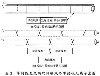
Figure 3(a) is a schematic diagram of the actual structure and working. Figure 3(b) is a schematic diagram of the transmission lines L0, L1, transmitting antenna, and receiving antenna tiled for the convenience of analysis. In practical applications, W = 20cm.
3.2 Analysis of transmission line reception interference suppression
When a signal current is added to the transmitting antenna on the locomotive, the central control room receives the signal from the communication transmission line. In order to suppress interference noise, the communication transmission line L0 is crossed at a certain distance W. From a long distance, it is a pair of twisted pairs. , its effect of suppressing interference noise can reach several dB to 30dB, with an average of 15dB [7].
For communication signals, according to equation (3), the amplitude AL0 of the induced signal on the communication transmission line L0 is a function of the antenna position x. When the center of the transmitting coil is aligned with any intersection point on L0, AL0 = 0, and a channel dead zone appears. In order to avoid this situation, another pair of communication transmission lines L1 is arranged in the coding cable, and its intersection point is staggered with L0, see Figure 3. Let d0 and d1 respectively represent the distance between the regional center lines of the L0 transmission line and the L1 transmission line where the transmitting coil position x is offset by x, then r = d0 + d1. Let eL0 represent the signal induced by transmission line L0, and eL1 represent the signal induced by transmission line L1. In the central control room electronic equipment, the signals e'L1 and eL0 after eL1 is phase-shifted by 90° are summed to obtain the composite signal e. According to formula (2), we get:
?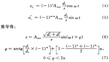
The amplitude A of the composite signal e is derived with respect to d0 ![]() , and it is found that it has a minimum value when d0=d1=r/2
, and it is found that it has a minimum value when d0=d1=r/2 ![]() . At this time, the transmitting antenna is in the most unfavorable position. The vector diagram of e is shown in Figure 4.
. At this time, the transmitting antenna is in the most unfavorable position. The vector diagram of e is shown in Figure 4.

The above analysis shows that using the crossed dual transmission line reception shown in Figure 3 has a strong effect on suppressing interference noise. For communication signals, when the transmitting antenna is in the most unfavorable position, there is 3dB attenuation.
3.3 Analysis of interference suppression when receiving by receiving antenna
Regarding interference noise, the traditional receiving antenna is a single coil without crossing and has no anti-interference ability. The receiving antenna shown in Figure 3 has receiving coil 1 and receiving coil 2 crossing each other. When working on site, the interference noise induced by the two coils The electromotive forces eN1 and eN2 have opposite phases. If the noise electromagnetic waves are uniformly distributed within a small range of 2W along the x direction of the receiving antenna, then eN1 = -eN2, and the noise electromotive force extracted by the receiving antenna eN = eN1 + eN2 = 0.
For communication signals, the modulated signal f0 to be sent from the central control room is amplified by power and sent from the transmission line L0; the signal f1 with a phase shift of 90° from f0 is amplified by power and sent from the transmission line L1. These two signals generate electromagnetic fields in the space near the coding cable. Synthesized, it is inductively received by the receiving antenna close to the coding cable. Since f0 and f1 are orthogonal, the channel dead zone is avoided. The induced signal generated in a traditional receiving antenna is described by equation (6). The receiving antenna shown in Figure 3 generates induced electromotive force e(1) and e(2) in receiving coil 1 and receiving coil 2. Due to the characteristics of same-spaced crossing, the receiving antenna has:
? (1)d0(1)=d0(2), d1(1)=d1(2), according to equation (6), the amplitudes of e(1) and e(2) are equal;
(2) If the electromagnetic field generated in the K region of the transmission line Li (i=0, 1) plays a dominant role in the receiving coil 1, then the electromagnetic field generated in the K+1 region plays a dominant role in the receiving coil 2. Due to the intersection of the transmission lines, the electromagnetic field generated in the K+1 region The phase of the electromagnetic field generated in the K region is opposite. The receiving coil 2 crosses the receiving coil 1. After two inversions, the phases of e(1) and e(2) are the same.
Therefore, the induced electromotive force e=e(1)+e(2)=2e(1) extracted by the receiving antenna from the communication signal is twice that of the traditional receiving antenna.
In addition, when the sending coil is sending a signal, the voltage at both ends of the sending coil is 200Vp-p. In order to prevent the receiving coil from sensing the strong signal sent and damaging the receiving preamplifier circuit, the sending coil is placed between the two coils of the receiving antenna. In this way, the receiving coil The electromotive force induced by the antenna to send the antenna signal is approximately zero.
3.4 Experimental analysis of receiving antenna interference suppression
The experimental conditions are: the total length of the transmission line is 3m, W=20mm. Using a set of actual induction wireless data communication equipment, the communication rate is 4800b/s, the modulation method is FSK, and the carrier frequency is 49KHz. During normal operation, the peak value of the modulated signal current passing through L0 is 0.07A; the peak value passing through the transmitting antenna coil The modulation signal current peak value is 0.38A.
During the experiment, keep the distance z = 200mm between the sending coil and the encoding cable, and keep the center of the sending coil aligned with L0 and cross without moving. In this case, the measured voltage amplitude of the induced signal on the transmission line L1 VL1 = 25mVP-P and the voltage amplitude of the induced signal on the receiving antenna VA = 20mVP-P.
If a signal generator is used as the interference source, a pair of parallel wire couplings are used for interference, as shown in Figure 5. The signal generator outputs interference voltage v=Vmsin2πft, f=49KHz, R=130Ω.
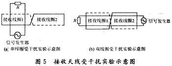
The experiment shown in Figure 5(a) is equivalent to the interference of a traditional receiving antenna. The experiment shown in Figure 5(b) is the situation where the cross coil of the receiving antenna is interfered. Assume that the interference induced electromotive force extracted from the receiving antenna is VNm (peak - peak). Table 1 gives the data from the two experiments.
Experimental results show that its ability to suppress interference noise reaches as much as 48dB.
The above theoretical and experimental analysis shows that the use of crossed receiving antennas with the same spacing not only has a strong effect on suppressing interference noise, but also has a 6dB gain in communication signals compared to traditional receiving antennas, greatly improving the signal-to-noise ratio.
? 
4 Conclusion
The interference suppression technology of "dual transmission lines and single receiving antennas crossing at the same distance" has been applied to the mobile locomotive computer centralized control management system composed of inductive wireless technology, and has been actually used in many industrial sites such as the coking plant of Laiwu Iron and Steel Company. In application, it can indeed suppress industrial site interference, especially the same-frequency interference generated by variable frequency speed control devices, ensuring the reliability of data communication. Of course, the inductive wireless data communication interference suppression technology proposed in this article only suppresses interference noise at the receiving end. Electronic equipment working in harsh industrial sites must also take measures such as grounding and shielding, which is beyond the scope of this article.
Previous article:Optical communication terminology that electronic design engineers will use throughout their lives
Next article:Design of train communication network card based on SOPC
- Popular Resources
- Popular amplifiers
-
 Mission-oriented wireless communications for cooperative sensing in intelligent unmanned systems
 -
 CVPR 2023 Paper Summary: Transparency, Fairness, Accountability, Privacy, Ethics in Vision
 -
 CVPR 2023 Paper Summary: Embodied Vision: Active Agents, Simulation
 -
 ICCV2023 Paper Summary: Fairness, Privacy, Ethics, Social-good, Transparency, Accountability in Vision
- Molex leverages SAP solutions to drive smart supply chain collaboration
- Pickering Launches New Future-Proof PXIe Single-Slot Controller for High-Performance Test and Measurement Applications
- CGD and Qorvo to jointly revolutionize motor control solutions
- Advanced gameplay, Harting takes your PCB board connection to a new level!
- Nidec Intelligent Motion is the first to launch an electric clutch ECU for two-wheeled vehicles
- Bosch and Tsinghua University renew cooperation agreement on artificial intelligence research to jointly promote the development of artificial intelligence in the industrial field
- GigaDevice unveils new MCU products, deeply unlocking industrial application scenarios with diversified products and solutions
- Advantech: Investing in Edge AI Innovation to Drive an Intelligent Future
- CGD and QORVO will revolutionize motor control solutions
- Innolux's intelligent steer-by-wire solution makes cars smarter and safer
- 8051 MCU - Parity Check
- How to efficiently balance the sensitivity of tactile sensing interfaces
- What should I do if the servo motor shakes? What causes the servo motor to shake quickly?
- 【Brushless Motor】Analysis of three-phase BLDC motor and sharing of two popular development boards
- Midea Industrial Technology's subsidiaries Clou Electronics and Hekang New Energy jointly appeared at the Munich Battery Energy Storage Exhibition and Solar Energy Exhibition
- Guoxin Sichen | Application of ferroelectric memory PB85RS2MC in power battery management, with a capacity of 2M
- Analysis of common faults of frequency converter
- In a head-on competition with Qualcomm, what kind of cockpit products has Intel come up with?
- Dalian Rongke's all-vanadium liquid flow battery energy storage equipment industrialization project has entered the sprint stage before production
- Allegro MicroSystems Introduces Advanced Magnetic and Inductive Position Sensing Solutions at Electronica 2024
- Car key in the left hand, liveness detection radar in the right hand, UWB is imperative for cars!
- After a decade of rapid development, domestic CIS has entered the market
- Aegis Dagger Battery + Thor EM-i Super Hybrid, Geely New Energy has thrown out two "king bombs"
- A brief discussion on functional safety - fault, error, and failure
- In the smart car 2.0 cycle, these core industry chains are facing major opportunities!
- The United States and Japan are developing new batteries. CATL faces challenges? How should China's new energy battery industry respond?
- Murata launches high-precision 6-axis inertial sensor for automobiles
- Ford patents pre-charge alarm to help save costs and respond to emergencies
- New real-time microcontroller system from Texas Instruments enables smarter processing in automotive and industrial applications
- Free Download | Maxim Reference Design Download for Industrial Applications
- Analysis of common causes of copper shedding in PCB factories
- 【micropython】Bluetooth BLE routine
- Suggestions on power consumption test of GD32L233C-START evaluation board
- RISC-V ESP32-C3 will become the new ESP8266
- Matters needing attention in the production of high-frequency microwave boards
- eMMC Summary (Forwarded)
- (Reprinted) Introduction to nRF5 chip peripherals GPIO and GPIOTE
- 【Project source code】Design of XPT2046 touch controller based on FPGA
- MCU restart freeze problem help

 Mission-oriented wireless communications for cooperative sensing in intelligent unmanned systems
 CVPR 2023 Paper Summary: Transparency, Fairness, Accountability, Privacy, Ethics in Vision


 京公网安备 11010802033920号