1. Introduction
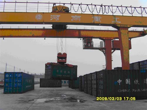
Container loader is one of the special container loading and unloading equipment. It can be used for loading, unloading, transshipment and stacking of 20ˊ and 40ˊ international standard containers. Its operating height can reach "six stacks and seven over". In order to improve the starting torque, traditional container loader adopts winding asynchronous motor to drive, and changes the speed of its rotor series resistance by operating the drum cam controller. With the development of power electronics technology and the emergence of vector control technology, people now generally use frequency converters as speed control power supplies, use multi-pole variable frequency asynchronous motors to replace the original winding asynchronous motors, and use PLC as the control device for contactless control. Thereby improving the speed regulation performance and increasing the reliability of the system. This article takes the successful application of CHV100 in the freight station of Ganzhou Railway Bureau as an example to explain the variable frequency speed regulation process of container loader.
2. System Introduction
2.1 Composition of the operating mechanism of container handling machine.
It mainly consists of three parts: trolley towing system, small car towing system and hook towing system.
(1) The trolley dragging system drags the entire crane to move left and right along the workshop direction (with the driver's sitting direction as a reference)
(2) The trolley dragging system drags the hook and the weight to move forward and backward along the bridge.
(3) The hook dragging system drags the weight to move up and down to lift or lower. The following introduces the hook dragging system.
2.2 Load characteristics
The operating mechanism of the container loading and unloading machine is a constant torque load, and its hook drag system is a potential load. When the hook lifts the weight and lowers it or decelerates rapidly, the motor is in a regenerative braking state. The electric energy needs to be fed back to the grid through the feedback device or consumed in the braking resistor to prevent the bus voltage from overshooting and the inverter from overvoltage.
3. Control requirements
3.1 The hook dragging system requires large starting torque and smooth starting operation. It should be able to realize forward and reverse operation and have multiple protections such as overload, limit, and current limit.
3.2 The hook dragging system is prone to the problem of "hook slipping" during the starting and stopping process.
Since the action process of the brake from clamping to releasing, and from releasing to clamping takes time (about 0.6s), the generation or disappearance of the motor torque reacts immediately at the moment of power on or off. Therefore, it is very easy for the brake and the motor to have problems in the coordination of action. If the motor is powered on and the brake has not been released, the motor will be seriously overloaded; conversely, if the motor is powered off and the brake has not been clamped, the weight will inevitably slide down, which is the so-called "hook slipping" phenomenon. Therefore, corresponding preventive measures must be taken.
3.3 There must be a mechanical brake device (mechanical brake) in the hook dragging system. When a heavy object is suspended in the air and there is a sudden power outage, if a mechanical brake device is not installed, the heavy object will be in danger of sliding down. Therefore, a brake must be installed on the hook motor shaft. Commonly used ones are electromagnetic brakes and hydraulic electromagnetic brakes.
4. System structure and control principle
4.1 System composition
4.1.1 Selection of frequency converter.
The trolley (translation mechanism) towing system of the container loader does not have high requirements on system performance. In order to save costs, the V/F control mode general inverter INVT-CHF100 can meet the requirements. (This article is simple); the loader hook (lifting mechanism) towing system requires higher starting torque and speed regulation performance, and a vector control inverter must be used. This article uses the INVT-CHV100 series vector inverter. The CHV100 series inverter has the following technical features:
a. Starting torque: 0.5Hz/150% (SVC) without PG vector control; 0Hz/180% (VC) with PG vector control (zero speed full torque function, also known as zero servo function, that is, at zero speed the motor can still output 180% of the rated torque to stop the heavy object in the air).
b. Overload capacity: 150% rated current for 60s; 180% rated current for 10s
c. Speed ratio: vector control without PG: 1:100; vector control with PG: 1:1000
d. Speed control accuracy: vector control without PG: ±0.5% of the maximum speed; vector control with PG: ±0.1% of the maximum speed.
The power of the hook lifting motor is: 75kw. In order to ensure sufficient starting and running torque, the capacity of the inverter is enlarged by one specification. Select: INVT-CHV100-090G-4 inverter + I/O expansion card. In order to save costs and simplify the control system, this solution adopts the control method of vector control without PG.
4.1.2 Selection of PLC and HMI
FX2N-40MR from Mitsubishi of Japan; MT506LV touch screen from Weilun of Taiwan
4.1.3 Selection of brake unit
The inverter's braking unit should be increased by one level to allow for a larger braking current and shorten the braking process; the rated power of the braking resistor should be doubled. Therefore, DBU-055-4 (2 in parallel) and braking resistor: 13.6Ω/9600W (2) are selected. (You can also increase one specification and directly select the energy feedback unit: RBU-110-4.)
4.2 System control principle
4.2 System control principle description
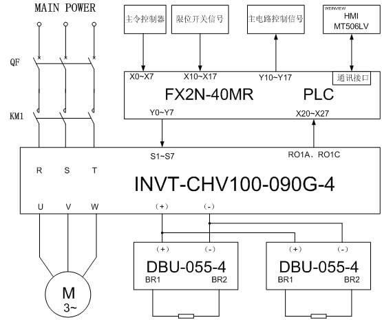
4.2.1 The master switch, overload, limit switch and inverter relay output signal 1 (fault output) are used as input signals for Mitsubishi FX2N plc.
The output signal of PLC controls the multi-function input terminal of the inverter (controls the inverter's forward and reverse rotation, multi-speed, fault reset, emergency stop, etc.) and the on and off of the main power circuit.
The touch screen and PLC are connected via the RS422 serial interface. The interface program in the PLC sets up a data reading area and related status signs for the touch screen in the PLC to monitor the height, load, operating status, fault information, etc. of the main hook.

(1-1) System control schematic diagram
5. Inverter wiring, debugging points and parameter settings
5.1 Inverter wiring instructions
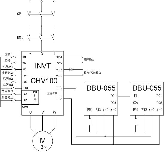
5.1.1 The inverter multi-function input terminals S1-S7 and HDI are used to control the inverter's start, stop, forward, reverse, multi-speed, fault reset, and emergency stop.
5.1.2 The output of relay 1 is used as a "fault output"; the output of relay 2 (FDT level output) is used as a "brake/release" signal output.
5.1.3 Two DBU-055-4 brake units and brake resistors are connected in parallel on the inverter DC bus to consume the energy generated during the hook's downward movement and realize the inverter's four-quadrant operation.

(1-2) Inverter wiring diagram
5.2 Debugging points
5.2.1 Manual Adjustment of Vector Parameters
Since the load cannot be separated on site and parameter self-learning cannot be performed, it is necessary to manually change the appropriate control parameters to optimize the control performance. Generally speaking, the following rules can be followed: if the low-frequency torque is insufficient, the stator resistance can be appropriately increased; if the slip rate is large, the rotor resistance can be appropriately increased. If the output voltage is low, the no-load current, stator and rotor inductance, and mutual inductance can be increased. In addition, the "current loop" and "speed loop" PI parameters can be appropriately adjusted, which will directly affect the dynamic response and control accuracy of the system.
5.2.2 Braking and releasing control
The vector control mode without PG cannot reach the rated output torque when running at "0" Hz, so it is necessary to use an FDT level (relay 2 output) function to improve the control function. That is: set a suitable FDT level detection value so that the inverter can open the mechanical brake device only after running at a certain frequency. If the FDT level detection value is set too high, it is easy to trip the "overload" or "overcurrent" fault; if the FDT level is set too low, it cannot lift heavy objects. The final FDT level detection value set here is 5Hz. If the vector control mode with PG is used, a control signal can be output to open the mechanical brake device when running at "0" Hz.
5.2.3 Dealing with the problem of hook slipping
In order to reduce the "hook slip" time of the system, try to set the deceleration time as short as possible, here it is set to 0.1s. In addition, the coordination of PLC and inverter timing logic is also very important.

5.3 Parameter settings
P0.00 0 No PG vector control
P0.01 1 Terminal command channel
P0.10 15 Keyboard set frequency
P0.11 1 Acceleration time 0
P0.12 0.1 Deceleration time 0
P0.14 2 Carrier frequency setting
P2.01 50 Motor rated frequency
P2.02 585 Motor rated speed
P2.03 380 Motor rated voltage
P2.04 168 Motor rated current P2.05
75 Motor rated power
P2.06 0.58 Motor stator resistance
P2.07 0.58 Motor rotor resistance
P2.08 17.4 Motor stator and rotor inductance
P2.09 18.5 Motor stator and rotor mutual inductance
P2.10 38.22 Motor no-load current
P3.14 170 Torque upper limit setting
P5.00 2 HDI1 is switch input
P5.02 1 Forward operation
P5.03 2 Reverse operation
P5.04 16 Multi-speed terminal 1
P5.05 17 Multi-speed terminal 2
P5.06 18 Multi-speed terminal 3
P5.07 19 Multi-speed terminal 4
P5.09 7 Fault reset
P5.10 6 Emergency stop
P6.04 3 Fault output
P6.05 6 Frequency level detection FDT output
P8.16 3 Fault automatic reset times
P8.18 0.1 Fault automatic reset interval time
P8.25 5 FDT level detection value
P8.26 2 FDT lag detection value
PA.06 40% Multi-speed 2
PA.14 60% Multi-speed 6
PA.16 80% Multi-speed 7
PA.32 100% Multi-speed 15
6. System
protection In this system, the inverter itself has multiple protection and fault output functions such as short circuit, overload, overvoltage, phase loss, stall, etc. For the hook dragging mechanism, the inverter drives a motor, so the output of the inverter can be directly connected to the motor without connecting a thermal relay for overload protection. The main circuit of the line is connected with a main
contactor
and a sub-contactor. In addition to the function of switching the circuit on and off, they also have multiple protections such as short circuit, overload, and undervoltage. The driver can control the main contactor and then control the switching of the main power supply through the start-stop button in the linkage console. When the circuit cannot be switched on and off by the contactor, the emergency stop switch can be used to connect the main circuit breaker shunt trip coil to disconnect the power circuit. In addition, the door limit switch and key switch are also connected in series in the main power control circuit as safety protection measures.
7. Conclusion
With the strong support of frequency converters and PLCs with complete functions and stable and reliable performance, container loaders have greatly improved in terms of reliability, speed regulation performance, energy saving and operating efficiency compared with traditional container loaders. The container loader system composed of frequency converters and PLCs has become a typical design model for container loaders and is being used more and more widely.
Previous article:Application of frequency converter in belt weighing feeding system
Next article:Application of Shenzhen Weikoda VB Servo in the Swing Arm of Box-type Cable Coil Forming Machine
Recommended ReadingLatest update time:2024-11-16 17:40

- Molex leverages SAP solutions to drive smart supply chain collaboration
- Pickering Launches New Future-Proof PXIe Single-Slot Controller for High-Performance Test and Measurement Applications
- CGD and Qorvo to jointly revolutionize motor control solutions
- Advanced gameplay, Harting takes your PCB board connection to a new level!
- Nidec Intelligent Motion is the first to launch an electric clutch ECU for two-wheeled vehicles
- Bosch and Tsinghua University renew cooperation agreement on artificial intelligence research to jointly promote the development of artificial intelligence in the industrial field
- GigaDevice unveils new MCU products, deeply unlocking industrial application scenarios with diversified products and solutions
- Advantech: Investing in Edge AI Innovation to Drive an Intelligent Future
- CGD and QORVO will revolutionize motor control solutions
- Innolux's intelligent steer-by-wire solution makes cars smarter and safer
- 8051 MCU - Parity Check
- How to efficiently balance the sensitivity of tactile sensing interfaces
- What should I do if the servo motor shakes? What causes the servo motor to shake quickly?
- 【Brushless Motor】Analysis of three-phase BLDC motor and sharing of two popular development boards
- Midea Industrial Technology's subsidiaries Clou Electronics and Hekang New Energy jointly appeared at the Munich Battery Energy Storage Exhibition and Solar Energy Exhibition
- Guoxin Sichen | Application of ferroelectric memory PB85RS2MC in power battery management, with a capacity of 2M
- Analysis of common faults of frequency converter
- In a head-on competition with Qualcomm, what kind of cockpit products has Intel come up with?
- Dalian Rongke's all-vanadium liquid flow battery energy storage equipment industrialization project has entered the sprint stage before production
- Allegro MicroSystems Introduces Advanced Magnetic and Inductive Position Sensing Solutions at Electronica 2024
- Car key in the left hand, liveness detection radar in the right hand, UWB is imperative for cars!
- After a decade of rapid development, domestic CIS has entered the market
- Aegis Dagger Battery + Thor EM-i Super Hybrid, Geely New Energy has thrown out two "king bombs"
- A brief discussion on functional safety - fault, error, and failure
- In the smart car 2.0 cycle, these core industry chains are facing major opportunities!
- The United States and Japan are developing new batteries. CATL faces challenges? How should China's new energy battery industry respond?
- Murata launches high-precision 6-axis inertial sensor for automobiles
- Ford patents pre-charge alarm to help save costs and respond to emergencies
- New real-time microcontroller system from Texas Instruments enables smarter processing in automotive and industrial applications
- 【Arduino】168 Sensor Series Experiments (214) --- 8x32-bit full-color WS2812B screen
- [RVB2601 Creative Application Development] +01 Unboxing and First Experience
- Urgently looking for! Texas Instruments Ti official website accounts registered before 2020 require registration with corporate email!
- Registration for the prize live broadcast is open | TOF (Time of Flight) technology introduction and product application
- Zero-knowledge open source sharing-the use of ESP8266WIFI module
- STM32CUBEMX generates EWARM V8 project, but cannot open the project
- Keysight Technologies' mid-year promotion for used instruments is intensifying
- Review summary: RTT & Renesas ultra-low power MCU RA2L1 development board
- System performance indicators of single-phase sine wave inverter
- PADS PCB board partial circuit replication

 Fundamentals of Analog Electronics Technology (Edited by Wu Tuo; Deputy Editors: Yi Yajun and Liu Sumei)


 京公网安备 11010802033920号