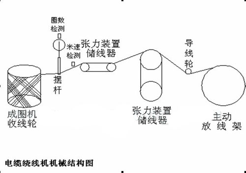
After the cable is released from the active pay-off rack, it passes through the tension device accumulator and is wound onto the expansion mandrel of the coil forming machine.
When the set length is reached, the coil forming machine stops automatically, the lower tray is lowered, and the packaging paper on the moving table is pushed under the coil line, and the coil line automatically falls into the paper box.
After the moving table is withdrawn, the lower tray rises to the working position and starts the next round of winding.
The swing arm in the whole process ensures the correct cross winding position and shape. The winding and pay-off tension is controlled constant by the tension arm of the wire storage device, and the active pay-off frame is synchronized. As shown in the figure:

Cable winding mechanical structure diagram
1. Process requirements:
a. The swing arm is synchronized with the coiling machine take-up wheel, and the cable density should be uniform;
b. The swing arm has 30 turns as one cycle. When it reaches 30 turns, it returns to the starting point to wind the second turn. A middle outlet hole is reserved. The outlet holes must be in the same position and cannot be pressed by the cable. It runs at 2 speeds until it reaches the predetermined number of meters and stops.
2. Servo function requirements:
a. Position control mode, tracking the speed of the coiling machine take-up wheel to achieve speed synchronization and cable density requirements;
b. Speed switching function, 30 turns as a cycle and reserved wire outlet hole position.
3. Control scheme and debugging instructions
:
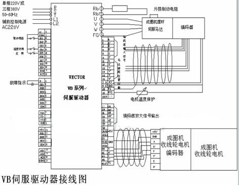
The coiling machine reel uses the Euro 514 series 2.2kW frequency conversion, which is mainly used for speed regulation of the coiling machine reel. The swing arm uses the Wekoda VB series servo driver to control the swing arm motor. The speed is adjusted according to the encoder given signal of the coiling machine reel and the encoder feedback signal of the swing arm motor to keep the synchronization of the cycloid and the reel. The speed is switched through the photoelectric switch to detect the number of circles and keep the position of the outlet hole. The system control is shown in the figure:

VB servo driver wiring diagram
Specific debugging parameter description of Weikoda VB series servo: (swing arm motor)
Restoring factory settings The following describes how to perform the actions and must be performed for every new drive:
1. Connect the drive to the power supply and turn on the power.
2. Set F.094=249.
3. Press the PAR key twice, then press the RESET key; the reset action will be executed.
4. The drive will automatically reset twice.
This completes the driver reset action, and the parameters are restored to factory values. Before self-learning of the driver and servo motor, please open the FR/W data setting (ie set F.095=0 and F.096=1).
H.450~H.499 are the parameters of permanent magnet brushless servo motor. (The motor should be disconnected from the load during self-learning).
1 Self-learning of permanent magnet brushless servo motor
Before self-learning, the following parameters must be set manually:
1. Set the motor rated speed to H.460 (rpm).
2. Set the motor rated current to H.461 = (motor rated current / drive rated current) × 100%.
3. Set the motor winding direction to H.492 = 1;
4. Set H.094 = 235.
5. Perform software or hardware reset to start self-learning.
During the self-learning operation, the driver will automatically detect the motor characteristics and automatically set the relevant motor parameters;
The drive will now automatically use motor parameter group #3 (H.450~H.499) to set the permanent magnet brushless servo motor parameters.
After the self-learning operation is completed, the driver will set F.094=232 and load the parameters related to the speed control mode of the permanent magnet brushless servo motor.
1. H.452 Encoder pulses per revolution (PPR).
2. H.453 Phase A leads or lags Phase B in forward rotation.
3. H.457 Motor rated voltage (motor rated voltage/input voltage).
4. H.458 Motor maximum voltage (same as H.457).
5. H.459 Torque boost voltage is set to 0.
6. H.462 Motor maximum current is set to 100%.
7. H.463 Excitation current is set to 0.
8. H.464 Number of motor poles.
9. H.465 Motor maximum allowable speed setting.
10. H.466 Motor minimum allowable speed is set to 0rpm.
11. H.467 Motor slip differential is set to 0.
12. H.470 Proportional gain of current control loop.
13. H.471 Integral gain of current control loop.
14. H.473 Proportional gain of the speed control loop.
15. H.474 Integral gain of the speed control loop.
2 Operation in position control mode
Set F.094=233, then execute the reset action, the CPU automatically sets the following parameters:
F.188=3 Select motor parameter group #3 (H.450~H.499)
H.450=3 Select permanent magnet brushless servo motor closed loop control
H.480=1 Select position control mode
H.481=1 Select tracking mode controlled by XY pulse input
H.482~H.483=0 No torque control
F.141=102 DI1 (102) drive is activated by DI1
F.145=73 DI5 (73) forward operation (when DI5 terminal is ON)
F.146=74 D16 (74) reverse operation (when DI6 terminal is ON)
F.181=0 & F.039=0.2 Operation command comes from keyboard
F.040=0.25 Speed input is set by F.000
F.000=500 Preset speed = 500rpm
F.130 = 0 Select quadruple rate XY pulse input
F.133 = 1000 XY pulse signal multiplication factor = 1000
F.134 = 1000 XY pulse signal division factor = 1000
Connect DI1 to COM to start the drive.
Press the FWD key on the keyboard, the driver receives the XY pulse signal, and the motor speed and direction are determined by the XY pulse signal.
Modify F.133 and F.134 and observe the impact of the pulse signal.
Then set the speed switching terminal F144=65 to switch the proportional coefficient of the 2-stage speed to reach the position of the reserved hole.
On-site debugging experiments have proved that after the box-type coil forming machine swing arm uses Shenzhen Weikoda VB series servo drive, the cable winding density is evenly arranged, the hole position is accurate, and the winding speed is also improved, which fully meets the process requirements of the box-type coil forming machine.
Previous article:Application of INVT-CHV100 in container handling machine
Next article:Application of Schneider ATV68 inverter in beer malt tower
- Molex leverages SAP solutions to drive smart supply chain collaboration
- Pickering Launches New Future-Proof PXIe Single-Slot Controller for High-Performance Test and Measurement Applications
- CGD and Qorvo to jointly revolutionize motor control solutions
- Advanced gameplay, Harting takes your PCB board connection to a new level!
- Nidec Intelligent Motion is the first to launch an electric clutch ECU for two-wheeled vehicles
- Bosch and Tsinghua University renew cooperation agreement on artificial intelligence research to jointly promote the development of artificial intelligence in the industrial field
- GigaDevice unveils new MCU products, deeply unlocking industrial application scenarios with diversified products and solutions
- Advantech: Investing in Edge AI Innovation to Drive an Intelligent Future
- CGD and QORVO will revolutionize motor control solutions
- Innolux's intelligent steer-by-wire solution makes cars smarter and safer
- 8051 MCU - Parity Check
- How to efficiently balance the sensitivity of tactile sensing interfaces
- What should I do if the servo motor shakes? What causes the servo motor to shake quickly?
- 【Brushless Motor】Analysis of three-phase BLDC motor and sharing of two popular development boards
- Midea Industrial Technology's subsidiaries Clou Electronics and Hekang New Energy jointly appeared at the Munich Battery Energy Storage Exhibition and Solar Energy Exhibition
- Guoxin Sichen | Application of ferroelectric memory PB85RS2MC in power battery management, with a capacity of 2M
- Analysis of common faults of frequency converter
- In a head-on competition with Qualcomm, what kind of cockpit products has Intel come up with?
- Dalian Rongke's all-vanadium liquid flow battery energy storage equipment industrialization project has entered the sprint stage before production
- Allegro MicroSystems Introduces Advanced Magnetic and Inductive Position Sensing Solutions at Electronica 2024
- Car key in the left hand, liveness detection radar in the right hand, UWB is imperative for cars!
- After a decade of rapid development, domestic CIS has entered the market
- Aegis Dagger Battery + Thor EM-i Super Hybrid, Geely New Energy has thrown out two "king bombs"
- A brief discussion on functional safety - fault, error, and failure
- In the smart car 2.0 cycle, these core industry chains are facing major opportunities!
- The United States and Japan are developing new batteries. CATL faces challenges? How should China's new energy battery industry respond?
- Murata launches high-precision 6-axis inertial sensor for automobiles
- Ford patents pre-charge alarm to help save costs and respond to emergencies
- New real-time microcontroller system from Texas Instruments enables smarter processing in automotive and industrial applications
- Don't understand antennas? Check this out
- FAQ_How to determine the phase of the output PWM signal in BlueNRG-12
- Tsinghua University professor Wang Zhihua: The demand for integrated circuit talents will increase 4.5 times by 2025 compared with 2020
- Why is the ADS of some MCU's display-related pins analog and DIR input?
- Open source Tinygo releases version 0.70
- Find a high quality coulomb counter
- First look at TMS320C5410
- [Mill MYB-YT507 development board trial experience] + build QT development environment and test, the most detailed steps to solve all troubles
- [Repost] Advantages and process of dry etching
- Microphone noise problem

 Automated Guided Vehicles in the Commercial Aircraft Industry


 京公网安备 11010802033920号