1 Introduction
In the field of industrial applications, most mechanical equipment uses advanced and practical control products to control the production process to improve the reliability and production efficiency of equipment operation. However, in the field of agricultural applications, due to the harsh operating environment of agricultural machinery and equipment and the low technical level of operators, most mechanical equipment does not use advanced control products, but uses traditional manual operation and relay control.
China is a large agricultural country, and agricultural machinery and equipment are spread all over the country. Applying control products with stable performance, reliable quality and powerful functions to agricultural machinery and equipment with a huge market will have a very positive impact on improving the automation level of China's agriculture and the market competitiveness of agricultural machinery enterprises.
This article introduces the application of Hollysys's new generation of small integrated PLC in agricultural hydraulic balers. This application has achieved good results in improving the automation of agricultural machinery and has great promotion value.
2 System Overview
Shandong Hydraulic Machinery Manufacturing Co., Ltd. is a leading domestic enterprise of hydraulic baling machinery. Its hydraulic balers are sold at home and abroad and have been widely praised by users. Hydraulic balers are widely used in the packaging of loose materials such as cotton fiber, flax, wool, paper edges, clothing, cloth, towels, wheat straw, etc., which provides great convenience for the storage and transportation of agricultural materials. Since hydraulic balers are generally used in harsh outdoor environments or seriously polluted production sites, high requirements are placed on control products. In the past, an automation company used a foreign brand PLC to transform the electrical control part of the hydraulic baler, but the application effect was poor. We conducted on-site inspections and repeated studies on the machine's operating environment, fully considered the harshness of the on-site environment, did a lot of work in reliability and stability, and proposed a control system based on the HOLLiAS-LEC G3 small integrated PLC. The actual operation effect shows that the control scheme has achieved the expected effect and greatly improved the automation level of the equipment.
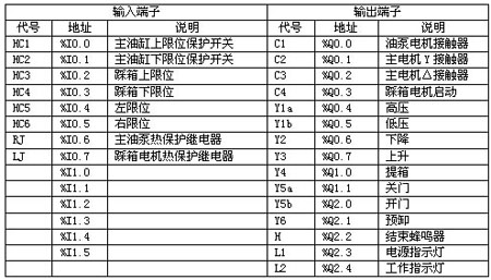
The hydraulic baler control system consists of a core control unit PLC and a human-machine interface for operation. The core control unit uses the G3 series small integrated PLC of Hollysys, and the human-machine interface uses the new generation text display MD204L of Shenzhen Human-Machine Electronics Co., Ltd. The PLC includes a 24-point CPU module LM3107 and an 8-way relay output module LM3222. The input and output signals are detailed in Table 1.

Table 1 I/O address allocation table
3 System Functions
The hydraulic baler controlled by PLC can realize functions such as automatic unpacking, automatic box lifting, automatic rotation, automatic cotton stepping, etc., and can monitor the production process in real time, complete functions such as automatic diagnosis, automatic alarm and data upload. In order to improve the reliability of the electrical control system, according to the actual needs of customers, all replaceable switch buttons that often fail are transferred to the human-machine interface, including the start/stop of the oil pump, the start/stop of the stepping box, the rise/fall/stop of the oil cylinder, the lifting box, the opening and closing of the door, etc. In addition, the time of the time relay is also set on the human-machine interface, including the oil pump motor start delay relay, the stepping box motor avoidance delay relay, the stepping box motor power-off delay relay and the oil cylinder rise buffer delay relay.
The control part of the hydraulic baler includes the oil pump motor control circuit, the box stepping motor control circuit, the lifting control circuit, the box lifting control circuit, the pre-unloading control circuit and the door opening and closing control circuit, etc. Each control circuit is introduced below.
Oil pump motor control circuit: through the text display control keyboard key operation, press the "pump start" oil pump motor start button, the main contactor C1 and Y contactor C2 are connected, and the oil pump motor starts the delay relay, and the time value on the text display is read and the timing is started. When the time is up, the Y contactor C2 is disconnected, and the △ contactor C3 is connected, and the C2 and C3 of the PLC are interlocked. Press the "pump stop" oil pump motor stop button, and the oil pump motor stops normally. When the motor is overloaded or blocked, the main oil pump thermal protection relay RJ switch is closed, and the main contactor C1 is immediately disconnected through the PLC program control and is in the protection state. After the fault is eliminated, restart and restart. When the oil cylinder exceeds the upper or lower limit, HC1 and HC2 must be protected in the PLC program control. By setting the value of the oil pump motor start delay relay, the Y-Δ start conversion time can be arbitrarily changed to ensure the best conversion state. Combined with multiple interlocking and self-locking, the normal starting and operation of the oil pump motor is completed, and an indicator light displays the operating status of the motor.
Stepping motor control circuit: Control the keyboard key operation through the text display, press the start button of the stepping motor "Step on", the stepping process begins, the stepping indicator light is on, the stepping motor contactor C4 is turned on, and the stepping motor avoidance delay relay reads the time value on the text display and starts timing. When the time is up, the internal intermediate relay of the PLC is triggered, the stepping is finished, the buzzer H is turned on to inform, and the stepping motor power-off delay relay reads the time value on the text display and starts timing. When the time is up, the cycle ends, and the stepping motor and buzzer H stop and reset. Press the stop button of the stepping motor "Step on Stop", all time relays and intermediate relays are reset, and the stepping motor stops. We can arbitrarily adjust the stepping motor avoidance delay relay and the stepping motor power-off delay relay with an accuracy of up to 1ms, and select different values according to different working conditions, which greatly facilitates user operation and significantly improves production efficiency.
Ascending and descending control loop: Ascending and descending are two opposite control processes, which are designed to be interlocked by the program to ensure uniform and safe actions. By controlling the keyboard key operation through the text display, press the "ascending" or "descending" button, and the box will move according to the program and start to ascend or descend to meet the process requirements.
Box lifting control circuit: The system box lifting control must be carried out after the ascent is completed. The key operations of the keyboard are controlled by the text display. Press the "box lifting" button and the box lifting begins. When the upper limit of the box is reached, the box lifting ends.
Unloading control loop: According to the process requirements, pre-unloading control must be carried out before the lifting or box lifting time period. The whole process of pre-unloading is completely automatically carried out by the PLC program. The pre-unloading process starts when the oil cylinder rises. Read the time setting value of the oil cylinder rising buffer delay relay on the text display, and start timing at the same time. When the time is up, the pre-unloading ends.
Door opening and closing control circuit: Door opening and door closing are two opposite control processes, which are controlled by the "open door" and "close door" operation buttons on the text display respectively. The internal intermediate relays ZJ6 and ZJ7 are interlocked to complete the door opening and closing actions respectively.

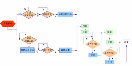
The system flow chart is shown in Figure 1.
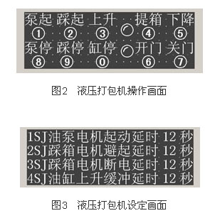
The main operation screen and time setting screen on the human-machine interface are shown in Figures 2 and 3.

4 Conclusion
The control system has been successfully applied to agricultural hydraulic balers, reducing the workload of operators, improving equipment operation efficiency and safety, reducing energy consumption, and improving product quality. Judging from the operation of the hydraulic balers on site, Hollysys's small integrated PLC is reliable in quality, stable in operation, and has good operating results. It can adapt to the harsh environment of agricultural machinery sites, and has achieved good results in improving the automation of agricultural machinery equipment, and has great promotion value.
Previous article:Unmanned monitoring system of oil depot based on PLC and KingView
Next article:PLC-based rooftop air conditioner with fresh air heat pump
Recommended ReadingLatest update time:2024-11-16 22:00


- Popular Resources
- Popular amplifiers
- Molex leverages SAP solutions to drive smart supply chain collaboration
- Pickering Launches New Future-Proof PXIe Single-Slot Controller for High-Performance Test and Measurement Applications
- CGD and Qorvo to jointly revolutionize motor control solutions
- Advanced gameplay, Harting takes your PCB board connection to a new level!
- Nidec Intelligent Motion is the first to launch an electric clutch ECU for two-wheeled vehicles
- Bosch and Tsinghua University renew cooperation agreement on artificial intelligence research to jointly promote the development of artificial intelligence in the industrial field
- GigaDevice unveils new MCU products, deeply unlocking industrial application scenarios with diversified products and solutions
- Advantech: Investing in Edge AI Innovation to Drive an Intelligent Future
- CGD and QORVO will revolutionize motor control solutions
- Innolux's intelligent steer-by-wire solution makes cars smarter and safer
- 8051 MCU - Parity Check
- How to efficiently balance the sensitivity of tactile sensing interfaces
- What should I do if the servo motor shakes? What causes the servo motor to shake quickly?
- 【Brushless Motor】Analysis of three-phase BLDC motor and sharing of two popular development boards
- Midea Industrial Technology's subsidiaries Clou Electronics and Hekang New Energy jointly appeared at the Munich Battery Energy Storage Exhibition and Solar Energy Exhibition
- Guoxin Sichen | Application of ferroelectric memory PB85RS2MC in power battery management, with a capacity of 2M
- Analysis of common faults of frequency converter
- In a head-on competition with Qualcomm, what kind of cockpit products has Intel come up with?
- Dalian Rongke's all-vanadium liquid flow battery energy storage equipment industrialization project has entered the sprint stage before production
- Allegro MicroSystems Introduces Advanced Magnetic and Inductive Position Sensing Solutions at Electronica 2024
- Car key in the left hand, liveness detection radar in the right hand, UWB is imperative for cars!
- After a decade of rapid development, domestic CIS has entered the market
- Aegis Dagger Battery + Thor EM-i Super Hybrid, Geely New Energy has thrown out two "king bombs"
- A brief discussion on functional safety - fault, error, and failure
- In the smart car 2.0 cycle, these core industry chains are facing major opportunities!
- The United States and Japan are developing new batteries. CATL faces challenges? How should China's new energy battery industry respond?
- Murata launches high-precision 6-axis inertial sensor for automobiles
- Ford patents pre-charge alarm to help save costs and respond to emergencies
- New real-time microcontroller system from Texas Instruments enables smarter processing in automotive and industrial applications
- Participate in TE's prize-giving event and solve the problems of smart meters!
- WiFi remote control coffee shop equipment
- Oscilloscope test inductor saturation current and inductance value
- MTK7686 serial port transparent transmission
- 【Silicon Labs Development Kit Review】+Breathing Light Example
- Shouldn't the positive and negative power supplies of the op amp be connected in series to have a reference point?
- The amplifier has a high PSRR, so there is no need to worry about power supply variations?
- How to design the mobile phone power-on circuit
- Request expert explanation
- The output waveform of the Siler oscillator is asymmetrical up and down?

 Siemens PLC Programming Technology and Application Cases (Edited by Liu Zhenquan, Wang Hanzhi, Yang Kun, etc.)


 京公网安备 11010802033920号