introduction
Stepper motor As an actuator, it is widely used in various types of automatic control systems. It is an electromagnetic mechanical device that converts discrete electrical pulse signals into corresponding angular displacement or linear displacement. The angular displacement it outputs is proportional to the number of input pulses, and the speed is proportional to the pulse frequency. It is an incremental drive element whose output corresponds to the input pulse. However, due to its large step angle, it often cannot meet the requirements of certain high-precision positioning, precision machining, etc. Therefore, implementing subdivision drive is an effective way to reduce the step angle, improve the step resolution, and increase the smoothness of motor operation.
In practical applications, it is often required that the motor speed meet the requirements and the torque be large enough during operation. The speed and torque of the motor are a pair of contradictions. When the speed is the same, the starting torque of the motor must be smaller than the running torque. Therefore, in practical applications, the starting frequency and running frequency should be determined according to the motor load torque.
This article will give a design of a driver module based on the A3972 driver chip to meet the needs of precision positioning in actual production, and give a reasonable acceleration curve to solve the contradiction between the starting torque and speed of the motor.
A3972 control chip
A3972 is Allegro's 64-segment dual DMOS full-bridge micro-step PWM stepper motor driver integrated circuit. The CPU can control it through the clock, data, and strobe 3-wire serial port, including the setting of the direction, speed, and step method (segmentation) of the stepper motor . The control instruction is written in the form of serial data in the format of two words, one for the bridge current data word and the other for the control time data word. Its operating voltage can reach 50V and the drive current can reach 1.5A. One A3972 can drive a two-phase stepper motor .
A3972 has excellent characteristics. The SPWM current control circuit inside the chip can be set to work in full step, half step, 1/4 step, etc. through the serial port, up to 1/64 step, and the load current of each step can be set in increments of 1.56% of the maximum value. Its unique three current decay modes, slow, fast, and mixed, can make the stepper motor work under different loads and speeds, and can obtain a more ideal current waveform. In addition, it is easy to interface with the microcontroller and has flexible control methods.
The power driver of A3972 adopts DMOS structure and high-speed SPWM switching mode, so the power consumption is extremely small and basically no heat sink is required, which can reduce cost (remove the heat sink) and size.
A3972 can also provide comprehensive protection measures, including transient voltage suppression, overheat protection, current through prevention, undervoltage self-locking and other functions. Therefore, A3972 is a high-performance serial control stepper motor micro-stepping driver.
System hardware design
The design of this stepper motor driver module is applied to the card receiving and sending mechanism of the automatic card receiving and sending machine developed by this institute. According to the use requirements, the hardware design of the overall system can be roughly divided into the control part, the drive part, the switching part and the power supply part.
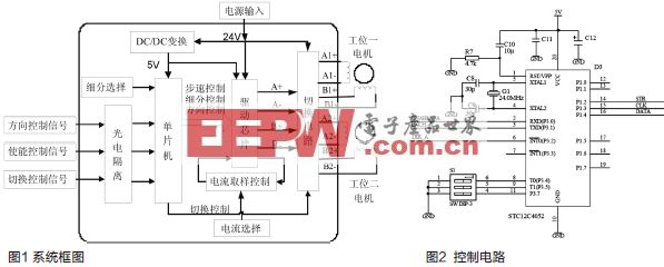
As shown in Figure 1, the system mainly consists of four parts: control, drive, switching and power supply.
Control Circuit
The control interface consists of three control signals, namely direction control signal, enable control signal and switching control signal. In practical applications, the high and low levels (5V) of these three control signals can be given as needed to conveniently and effectively control the operation of the motor.
The core of the control part is the single-chip microcomputer and its control software. It receives various control commands from the main controller of the automatic card receiving and sending machine through the optical isolation circuit. Combined with the setting of the subdivision selection switch, it controls the subdivision multiples, operating pulse frequency, forward and reverse rotation, operating speed, single operation line displacement, start and stop, and switching of motors at different workstations of the stepper motor through the 3-wire serial interface as required.
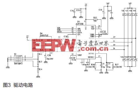
This part of the circuit is mainly composed of a single-chip microcomputer and its peripheral circuits (see Figure 2). The single-chip microcomputer selected is 8051 single-chip microcomputer STC12C4052, which has the advantages of high speed, high reliability, and in-system programmability. The S1 dip switch is a subdivision selection switch. According to the value of S1, the motor can be set to work in full step, half step, 1/4 step, 1/8 step, 1/16 step, 1/32, 1/64 and other modes through the serial port (STR, CLK, DATA).
Drive circuit

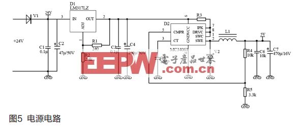
The driving part is the key to the reliable operation of the motor. In addition to completing the functions of driving the motor forward and reverse, accelerating and starting, and stopping according to the command, this part also needs to consider reducing power consumption and volume. The printed circuit board wiring should use a thick ground wire. A3972 is directly welded on the printed circuit board to improve the electrical performance and heat dissipation performance of the circuit.
The peripheral circuit of A3972 is simple, and only a few external components and a few control lines are needed to form a complete micro-step drive two-phase stepper motor circuit (see Figure 3). The dip switch S2 is used to set the maximum load operating current ITRIPMAX = VREF/(Range × Rs) of the bridge output. Different settings have different VREF values. If the first bit of the dip switch is turned on, VREF=1.25(1+R10/R11). The Range is determined by the control word 0. In this article, the Range value is 8 and the Rs value is 0.22Ω.
Switching Circuit
Since the design of the automatic card receiving and distributing machine is based on a dual-station (working channel), this driver module has a built-in motor switching circuit that can drive two motors working in time-sharing mode. The switching part consists of a low-power MOS transistor integrated chip and peripheral circuits (see Figure 4).
Power supply (DC/DC conversion) circuit
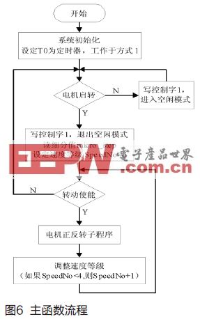
In order to make the control part of the module have a stable working environment (including voltage stability, anti-interference, etc.), the power supply part uses a small power DC/DC conversion chip to make a 24V-5V switching regulated power supply (non-isolated type) for the control part of the module. In addition, overvoltage protection and power direction protection circuits are added to improve reliability, as shown in Figure 5. V1 is an ultra-fast rectifier diode, which can play a role in power direction protection. The output voltage of D1 is VOUT=1.25(1+R2/R1), which provides a relatively stable and safe input voltage to D2, and then the voltage is converted to VOUT=1.25(1+R4/R5) or 5V through D2.
System software design
System software design is the key part of the design. Each rotation of the motor is achieved by the microcontroller software writing control word 0 and control word 1 to the driver chip, so the setting of the control word value is the key to the design. This article also gives a reasonable acceleration curve to solve the contradiction between the starting torque and speed of the motor.
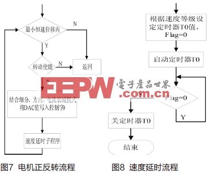
As shown in the motor forward and reverse rotation process in Figure 7, every time the motor rotates one microstep, two bridge currents need to be written into control word 0. The bridge current is determined by the 6-bit linear DAC value. The DAC value is written into the driver chip according to a certain rule in combination with the subdivision value, current direction and current attenuation mode.
The acceleration process of motor startup is divided into 5 speed levels. When the motor starts, the speed level SpeedNo is set to 0. The speed level is gradually increased with the minimum constant speed displacement as the unit, and the step speed is changed by setting the value of timer T0 as the time delay between two microsteps. In the speed delay process in Figure 8, Flag is the delay end flag, which is set when timer T0 overflows.
Conclusion
The driver module has been used in the automatic card receiving and distributing machine project developed by our institute to drive the 42 series two-phase stepper motor with a step angle of 1.8°. In order to further improve the positioning accuracy of the stepper motor and the smooth operation of the system, the subdivision level is 16. From the actual operation, the stepper motor driver has achieved a high steady speed accuracy, reliable operation, and achieved satisfactory results.
Previous article:Discussion on Anti-interference Problem in Frequency Converter Application
Next article:Design and application of frequency conversion speed regulation system for cooling fan of main transformer in substation
Recommended ReadingLatest update time:2024-11-16 16:46


- Popular Resources
- Popular amplifiers
-
 西门子S7-12001500 PLC SCL语言编程从入门到精通 (北岛李工)
 -
 Small AC Servo Motor Control Circuit Design (by Masaru Ishijima; translated by Xue Liang and Zhu Jianjun, by Masaru Ishijima, Xue Liang, and Zhu Jianjun)
 -
 Intelligent Control Technology of Permanent Magnet Synchronous Motor (Written by Wang Jun)
 -
 100 Examples of Microcontroller C Language Applications (with CD-ROM, 3rd Edition) (Wang Huiliang, Wang Dongfeng, Dong Guanqiang)
- Molex leverages SAP solutions to drive smart supply chain collaboration
- Pickering Launches New Future-Proof PXIe Single-Slot Controller for High-Performance Test and Measurement Applications
- CGD and Qorvo to jointly revolutionize motor control solutions
- Advanced gameplay, Harting takes your PCB board connection to a new level!
- Nidec Intelligent Motion is the first to launch an electric clutch ECU for two-wheeled vehicles
- Bosch and Tsinghua University renew cooperation agreement on artificial intelligence research to jointly promote the development of artificial intelligence in the industrial field
- GigaDevice unveils new MCU products, deeply unlocking industrial application scenarios with diversified products and solutions
- Advantech: Investing in Edge AI Innovation to Drive an Intelligent Future
- CGD and QORVO will revolutionize motor control solutions
- Innolux's intelligent steer-by-wire solution makes cars smarter and safer
- 8051 MCU - Parity Check
- How to efficiently balance the sensitivity of tactile sensing interfaces
- What should I do if the servo motor shakes? What causes the servo motor to shake quickly?
- 【Brushless Motor】Analysis of three-phase BLDC motor and sharing of two popular development boards
- Midea Industrial Technology's subsidiaries Clou Electronics and Hekang New Energy jointly appeared at the Munich Battery Energy Storage Exhibition and Solar Energy Exhibition
- Guoxin Sichen | Application of ferroelectric memory PB85RS2MC in power battery management, with a capacity of 2M
- Analysis of common faults of frequency converter
- In a head-on competition with Qualcomm, what kind of cockpit products has Intel come up with?
- Dalian Rongke's all-vanadium liquid flow battery energy storage equipment industrialization project has entered the sprint stage before production
- Allegro MicroSystems Introduces Advanced Magnetic and Inductive Position Sensing Solutions at Electronica 2024
- Car key in the left hand, liveness detection radar in the right hand, UWB is imperative for cars!
- After a decade of rapid development, domestic CIS has entered the market
- Aegis Dagger Battery + Thor EM-i Super Hybrid, Geely New Energy has thrown out two "king bombs"
- A brief discussion on functional safety - fault, error, and failure
- In the smart car 2.0 cycle, these core industry chains are facing major opportunities!
- The United States and Japan are developing new batteries. CATL faces challenges? How should China's new energy battery industry respond?
- Murata launches high-precision 6-axis inertial sensor for automobiles
- Ford patents pre-charge alarm to help save costs and respond to emergencies
- New real-time microcontroller system from Texas Instruments enables smarter processing in automotive and industrial applications
- Friends in Xi'an, please get out of this pit as soon as possible.
- Xianyu low-cost wireless digital microphone disassembly (Jerry solution)
- [Perf-V Review] + Solidification of Hummingbird Soft Core
- Read the good book "Electronic Engineer Self-study Handbook" + my impression
- Three-port network
- RSL10 drives ink screen
- GoKit Case Study: Gizwits IoT Development Platform’s Pet House Transformed into an Air Quality Detector
- Embedded licensing: why not and why not?
- I found a 1963 "Electron Tube Handbook"
- How to extract the effective value of fundamental wave and each harmonic in MATLAB?

 西门子S7-12001500 PLC SCL语言编程从入门到精通 (北岛李工)


 京公网安备 11010802033920号