At present, the servo system of our navy's naval guns still uses the early electromechanical equipment, which has the main disadvantages of large tracking and positioning errors, poor maneuverability, weak rapid penetration capability, large size, high noise, high price, and high failure rate. These problems directly affect the improvement of the ship's comprehensive defense capability and survivability. Therefore, it is very necessary to use computers to digitize the servo system of the naval gun.
1 Composition of a certain type of naval gun tracking system
The following description of the naval gun tracking system is based on the principle of deviation between the input angle and the feedback angle. Its structure is shown in Figure 1.

The firing parameters calculated by the director are transmitted to the receiver of the servo system. The receiver compares the future position of the target given by the director with the actual position of the gun to obtain the error voltage u θ . After signal selection and AC amplification , u θ enters the phase-sensitive rectifier to demodulate the DC signal voltage U θ related to the size and direction of uθ . After correction by the position regulator, it enters the speed regulator and is added with the speed feedback signal u f and the current feedback signal If to form the control signal of the motor amplifier, which controls the size and polarity of the voltage at the terminal of the amplifier motor, thereby controlling the speed and direction of the actuator motor.
The tachometer generator that rotates coaxially with the execution motor generates a speed feedback signal, which is sent to the input of the speed regulator through the filter network. The current feedback signal taken from the compensation winding of the motor amplifier is also sent to the input of the speed regulator and superimposed with the main command signal, so that all parts after the position regulator together form a high-performance speed regulation system. The PI regulator and the reduction circuit are used in the position regulator, and the position regulator can be automatically switched to work in the PI regulation state or the P regulation state according to the size of the error. In addition, the system also introduces a signal proportional to the target operating speed from the director, that is, the feedforward signal, which is differentiated by the RC network and added to the position regulator to compensate for the error caused by acceleration.
The following shortcomings exist in this servo system:
(1) The power drive link uses the most primitive alternating magnetic motor amplifier, which requires an electric motor to provide driving power. It is complicated to use and maintain, and is extremely unsuitable for daily military training and equipment maintenance.
(2) The alternating magnetic motor amplifier is an inertial link, which affects the system's real-time fast processing capability and has a slow dynamic response.
(3) It is large in size, noisy, and inefficient.
(4) The peripheral circuit is complex and has low reliability.
In view of the above shortcomings, in order to facilitate the use and maintenance of the troops, the servo system was digitally improved with DSP as the core and the latest PWM control technology. The main purpose is to replace the alternating magnetic motor amplifier with a digital motor drive amplifier circuit.
2 Digital improvement of the servo system
The improved system is shown in Figure 2, which is mainly composed of a main control computer combination, an IPM module that drives the execution motor, azimuth and height position feedback, azimuth and height execution motors, azimuth and height zero position indicators, speed and current feedback circuits, and firing control circuits.

2.1 Basic Principles
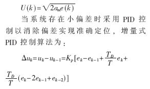
The main control computer compares the target future point position signal transmitted by the director with the current position signal of the gun, performs variable structure control, and outputs a given speed signal, that is, a combination of nonlinear square root control and linear PID control is adopted.
When the system has a large deviation (00~10), square root control is used to ensure the rapidity of the system. The control algorithm is:

The given speed signal is compared with the speed feedback signal, and the given current signal is output after PI adjustment.
The given current signal is compared with the current feedback signal, and the required PWM control signal wave is output after PI adjustment, and then output to the corresponding control terminal of the IPM through high-speed optical coupler isolation.
In this way, the IPM can be driven to work according to the control requirements, thereby driving the execution motor to drive the ship's gun to track the target.
2.2 Main control computer combination working process
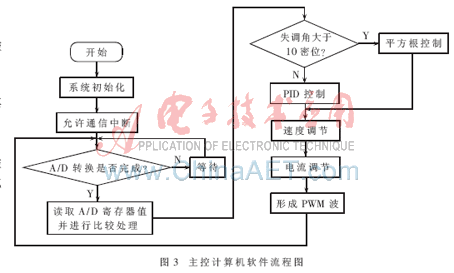
The main control computer combination is a fully digital module with TMS320F2407 as the core, and has interfaces such as multi-channel PWM output, current detection, encoder interface, communication interface, analog input and output, digital I/O, and various fault diagnosis and alarm functions. The solution process is shown in Figure 3.

2.3 Working Principle of Power Amplifier Circuit
The improved power amplifier circuit uses a dual H-bridge to replace the alternating magnetic motor amplifier in the original system to drive two actuator motors respectively, as shown in Figure 4. The switching devices V1, V2, V3, and V4 in the H-bridge use intelligent power modules (IPMs), and the module model used in this system is PM200DSA06.

The DC power supply is obtained by rectifying the three-phase AC power through a thyristor. The output terminal is connected to the execution motor. The set control pulse is input into the control terminal of each IPM module. In order to prevent the mutual interference between the strong current part (IPM) and the weak current part (control signal PWM wave), a high-speed optocoupler is used here to complete the electrical isolation, as shown in Figure 2. In addition, the IPM module also has a fault output terminal, which is connected to the main control computer terminal through an optocoupler. Once the module fails, the main control computer immediately applies for a high priority interrupt, stops the output of the control signal, and stops the IPM from working.
2.4 Feedback Circuit Design
2.4.1 Current Detection Circuit
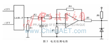
The current detection circuit uses the Hall current sensor LA58-P as the current detection element to detect the armature current of the motor. The transformation ratio of LA58-P is 1:1 000. Since the D input signal required by TMS320F2407 is a 0-5 V analog voltage signal, the weak current signal output by the current sensor is first converted into a voltage signal through the sampling resistor R1, and then filtered by the RC circuit, and then scaled through the operational amplifier to convert it into a 0-5 V voltage signal and sent to the A/D acquisition channel of the DSP. The current detection circuit is shown in Figure 5.

2.4.2 Principle of Gun Position Detection
The position detection element occupies a very important position in the servo system. Its detection accuracy is directly related to the operation accuracy of the entire system. Therefore, this servo system uses an absolute position detection element - a multi-pole rotary transformer to detect the angle, convert the system output angle into an analog voltage value, and then use the shaft encoder to encode the shaft angle, convert the gun position signal into a binary code, and send it to the main control computer to achieve position feedback.
3 Performance comparison before and after improvement
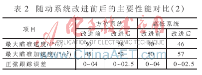
Based on the above scheme, the improved servo system has significantly improved the performance in terms of turning speed, turning time and stable tracking speed, and the number of oscillations in the transition process has been significantly reduced. After the intelligent power module is used to replace the alternating magnetic motor amplifier, the rapid start performance of the digital servo system is improved. The main performance comparison of the servo system before and after improvement is shown in Table 1 and Table 2.


It can be seen from the above table that the maximum aiming speed of the improved gun tracking system in azimuth and elevation is increased by 16% and 15% respectively, the response time and the number of half-oscillations are significantly reduced, and the sinusoidal tracking error is reduced by 37.5%.
Experiments have proved that the improved method and technical implementation process are reasonable and feasible. Through this improvement, the tactical and technical performance of the ship gun tracking system is effectively improved, the combat performance and information level of weapons and equipment are improved, the difficulty of technical support is reduced, and the purpose of improvement is achieved. In summary, the main advantages of this improvement plan are:
(1) Compared with the original system, this DSP-based servo system has higher dynamic response performance and control accuracy.
(2) Since rotating equipment such as engines and alternating-magnetic motor amplifiers are no longer needed, the original functions can be completed by connecting to shore power during daily maintenance and training of the troops, reducing operating noise and improving the working environment.
(3) As the main control computer is highly integrated and uses an intelligent power module, the device is very small, only 1/5 of the size of the original motor amplifier, making it easy to make a sophisticated control box that can be directly installed on the motor housing, which is very suitable for fully enclosed naval guns with limited space.
(4) This DSP-based digital tracking system can also be applied to other naval guns, which is very beneficial for the digitalization of our naval equipment.
Previous article:Design of automatic voice broadcasting system for railway station signals
Next article:Research and Application of OPC Interface in PID Optimization Tuning System
- Popular Resources
- Popular amplifiers
- Molex leverages SAP solutions to drive smart supply chain collaboration
- Pickering Launches New Future-Proof PXIe Single-Slot Controller for High-Performance Test and Measurement Applications
- CGD and Qorvo to jointly revolutionize motor control solutions
- Advanced gameplay, Harting takes your PCB board connection to a new level!
- Nidec Intelligent Motion is the first to launch an electric clutch ECU for two-wheeled vehicles
- Bosch and Tsinghua University renew cooperation agreement on artificial intelligence research to jointly promote the development of artificial intelligence in the industrial field
- GigaDevice unveils new MCU products, deeply unlocking industrial application scenarios with diversified products and solutions
- Advantech: Investing in Edge AI Innovation to Drive an Intelligent Future
- CGD and QORVO will revolutionize motor control solutions
- Innolux's intelligent steer-by-wire solution makes cars smarter and safer
- 8051 MCU - Parity Check
- How to efficiently balance the sensitivity of tactile sensing interfaces
- What should I do if the servo motor shakes? What causes the servo motor to shake quickly?
- 【Brushless Motor】Analysis of three-phase BLDC motor and sharing of two popular development boards
- Midea Industrial Technology's subsidiaries Clou Electronics and Hekang New Energy jointly appeared at the Munich Battery Energy Storage Exhibition and Solar Energy Exhibition
- Guoxin Sichen | Application of ferroelectric memory PB85RS2MC in power battery management, with a capacity of 2M
- Analysis of common faults of frequency converter
- In a head-on competition with Qualcomm, what kind of cockpit products has Intel come up with?
- Dalian Rongke's all-vanadium liquid flow battery energy storage equipment industrialization project has entered the sprint stage before production
- Allegro MicroSystems Introduces Advanced Magnetic and Inductive Position Sensing Solutions at Electronica 2024
- Car key in the left hand, liveness detection radar in the right hand, UWB is imperative for cars!
- After a decade of rapid development, domestic CIS has entered the market
- Aegis Dagger Battery + Thor EM-i Super Hybrid, Geely New Energy has thrown out two "king bombs"
- A brief discussion on functional safety - fault, error, and failure
- In the smart car 2.0 cycle, these core industry chains are facing major opportunities!
- The United States and Japan are developing new batteries. CATL faces challenges? How should China's new energy battery industry respond?
- Murata launches high-precision 6-axis inertial sensor for automobiles
- Ford patents pre-charge alarm to help save costs and respond to emergencies
- New real-time microcontroller system from Texas Instruments enables smarter processing in automotive and industrial applications
- TRUWB digital receiver performance based on ADC and its FPGA implementation.pdf
- Can the number of pulses of an ultrasonic generator driven by a transformer be accurately controlled?
- The helper2416 development board driver failed to create a device node
- 【Chuanglong TL570x-EVM】Review 01 - Unboxing
- Power Factor Correction
- Ultra-low standby power consumption < 90mW non-auxiliary AC/DC power supply reference design
- 3D Printer Project—STM32F7508-DK Environment Creation (I)
- Looking for the movie download website of "Miracle"!
- mosfet discrete devices
- MSP430 MCU Development Record (21)

 Digilent Vivado library
 First Clinical Experience with Retrospective Flash Glucose Monitoring (FGM) Analysis in South Africa


 京公网安备 11010802033920号