In the past, when designing a power supply, power design engineers would spend a lot of time on model selection, circuit design and evaluation. Since power supply design involves EMI, efficiency, performance and cost, coupled with the continuous reduction of design cycles, it is difficult for engineers to have enough time to choose a product that best suits them.
Although there are various powerful offline evaluation tools and software, offline tools are relatively complex and lack effective and timely updates. Nowadays, with the rise of cloud computing, major power supply manufacturers have developed online design tools based on the Internet, which can greatly simplify the time for engineers to select and evaluate in the early stage of power supply design, and enhance the design efficiency of engineers.
Below we select the online design tools of three power supply design manufacturers and use actual cases to evaluate the characteristics of each company.
We are going to make a flyback power supply with an input of 85-265V and an output of 5V/2A, and do a horizontal evaluation. This article only represents personal opinions. Considering the different specific application scenarios, we also hope that readers can try it themselves.
ROHM Online Design Tool
First, let’s focus on ROHM’s online design tool: ROHM AC/DC Designer.
In the navigation bar of Rohm's official website, click Product Information, IC, Power Management, AC/DC Converter in turn to find the tool. Enter the parameters we need in the pink box below, click the Search button, and enter the next step of parameter search.
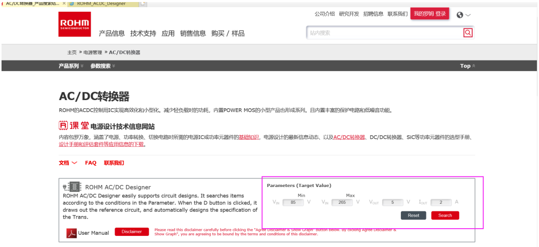
As the name suggests, since it is a parameter search, users can choose to enter their own filtering conditions to obtain a more accurate target design, or they can choose not to enter any parameters to give themselves more choices.

Continue browsing down to see a list of devices that meet the conditions according to the parameter settings and filtering conditions, and select the device that meets your design requirements. For this purpose, we select a device with overvoltage protection (restart) BM2P014, click the red button in the list, and the dialog box shown in the figure below will pop up. Continue to click the Design button to obtain the design results.

The design results are displayed to users in the form of schematic diagrams by default. Users can select "Calculation Reset", "BOM List", "Transformer Specification", "Design Results", "Download Design Options" according to their needs to view and download corresponding documents to assist in design.
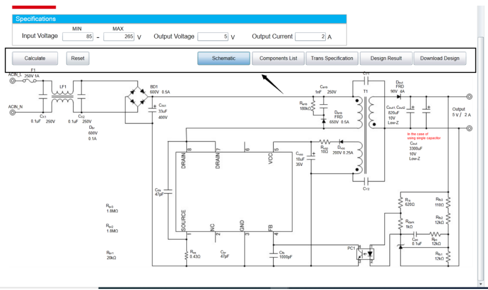
To sum up, the overall experience of using ROHM's online design software is: easy to operate, a simple design plan for peripheral components can be generated in just a few steps, and users can design a stable and reliable power supply based on the data sheet.
TI WEBENCH
Next, let’s experience TI WEBENCH® Power Designer.
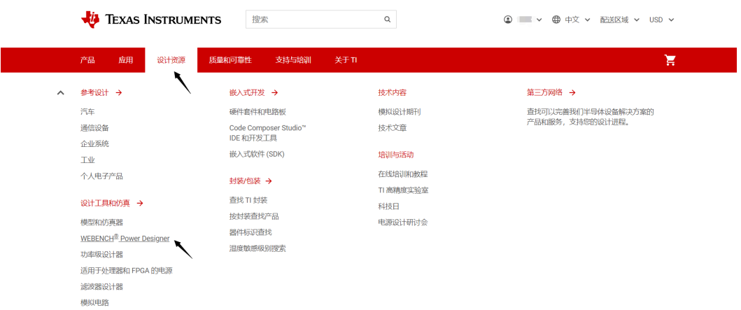
WEBENCH is relatively easy to find. Through the navigation bar of TI's official website, click Design Resources and WEBENCH Power Designer in turn to enter the design interface. It should be noted that to use this tool, users need to register a myTI account in advance.
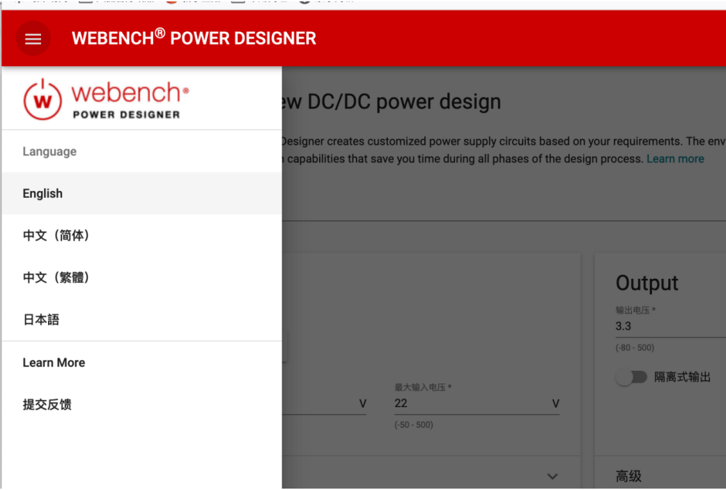
Unlike the product page of ROHM tools, WEBENCH has an independent tool interface, and the language can be easily switched through the left navigation bar.
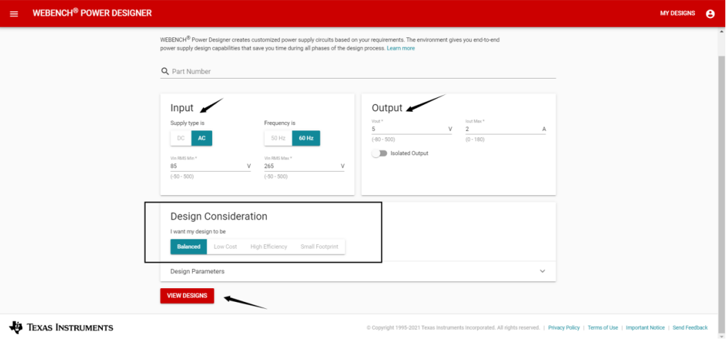
In the input bar in the upper left corner, select AC as the power type, set the parameters according to the design requirements: input voltage range, output voltage, output current, and in the design considerations, select balance, low cost, high efficiency, and small size according to the specific application scenario, and then click the VIEW DESIGNS button to enter the design results page.
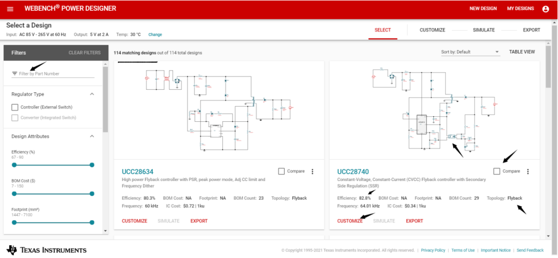
According to our design requirements, we obtained 114 reference designs and selected the following solutions: 82.8% efficiency, Flyback, and UCC28740.
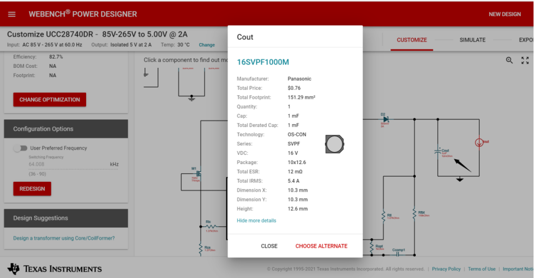
WEBENCH is very friendly in providing component information. Users can see detailed parameters and specifications by clicking on any component in the schematic. It also provides alternative options, so users can find alternative devices from other semiconductor manufacturers.
Finally, click Export to output the schematic, BOM, diagram and operating values of the solution we need to assist in the design.
To sum up, the overall feeling of using TI WEBENCH: the design scheme is more user-friendly, clearly marked, and easy to use. It is relatively easy for users to design a switching power supply that meets the requirements; the schematic component parameters are very detailed, allowing users to clearly know the parameter indicators of each device. The output design document also has test data, such as: current and temperature rise, output current and efficiency, output current and duty cycle curves, which are very complete; there are many design cases and a large selection space.
PI Expert
Finally, let's experience PI Expert. Since PI focuses on switching power supply solutions, users can find this design tool on the PI homepage, and the Chinese and English bilingual interface makes it more convenient for users to use. It should be noted that: to use this tool, users need to register a PI account in advance.
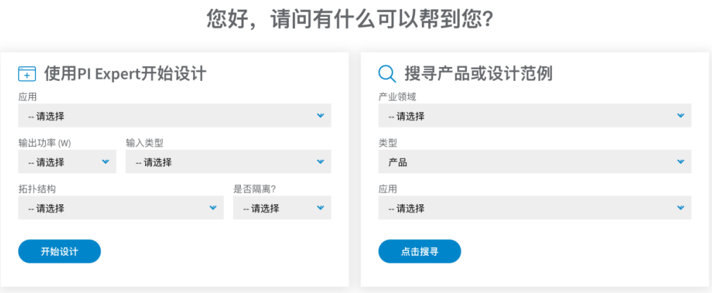
We click Start Design to enter the design interface.

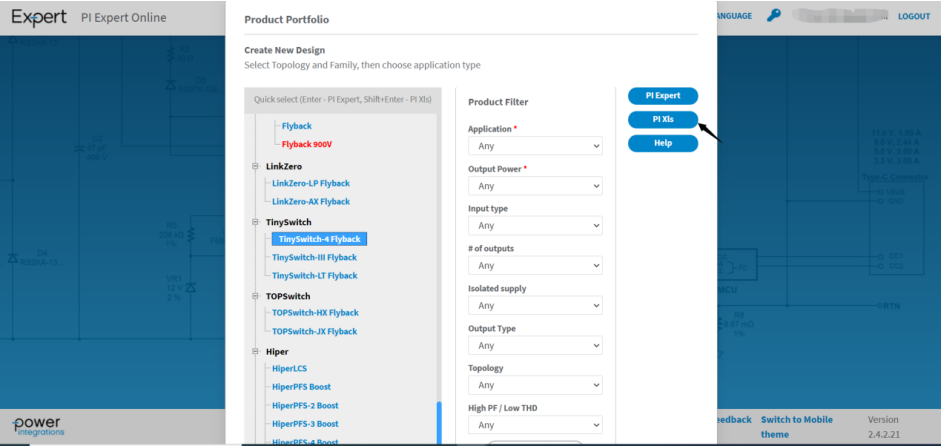
The first part on the left is the device list. Users can select product series based on their familiarity with PI products. The second part in the middle is the function filter. Users can let the system recommend design solutions based on their application scenarios. The third part on the right is the button to start the subsequent PI Expert design tool. The fourth part on the right is the "PI XLS" high-frequency transformer design button. Let's take the PI TinySwitch series as an example and click PI Expert to start our design.
The first step is to set options
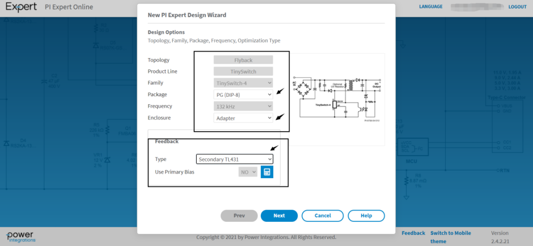
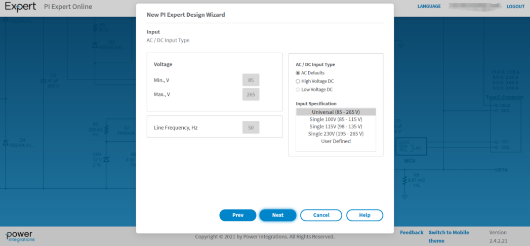
The parameters in the box can be selected by the user. We choose DIP package, 132kHz frequency, adapter type (this is done to adapt to poor heat dissipation or high temperature environment, users can choose open design according to their needs), feedback mode is secondary TL431, click "next" to set the input voltage on the pop-up page, we choose universal. Continue to the next step.
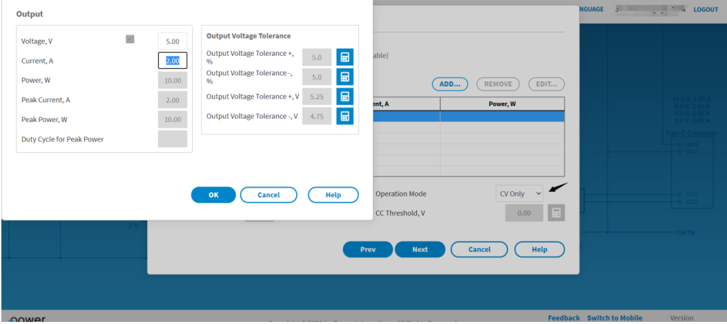
Next, enter the output voltage setting interface, click the "ADD" button, and a dialog box will pop up, where users can set the output voltage, current parameters, and output voltage accuracy. This section allows multiple output voltages, which is convenient for users with multiple output voltages. You can also set the total peak power, working mode, continuous power, etc. below. Here we choose CV mode and click "NEXT" to proceed to the next step.
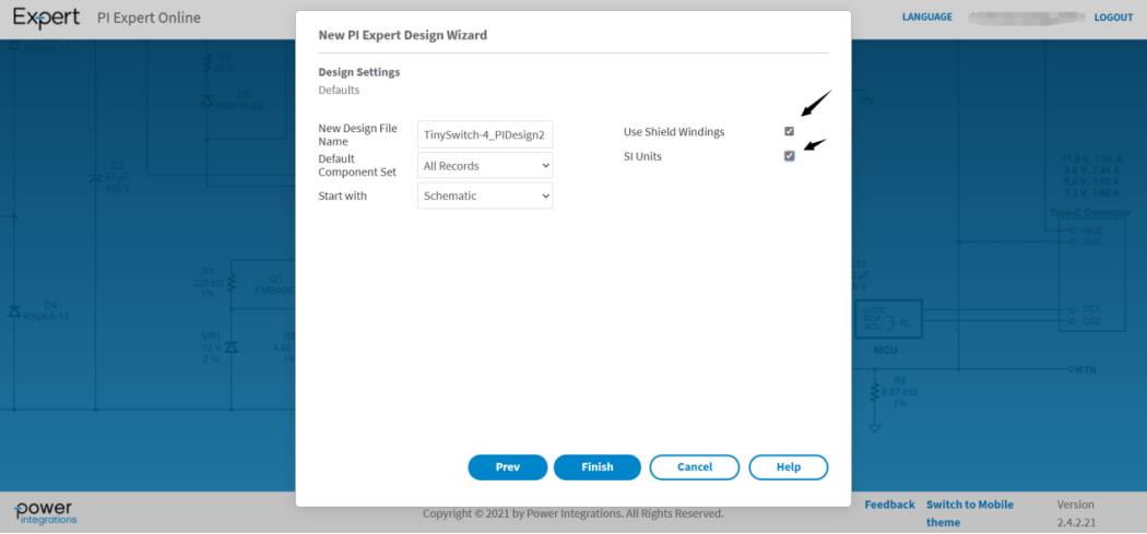
In the design settings interface, set the design name, default component set, start item, shield layer (no shield by default) and unit (US standard by default).
After clicking "finish", the TinySwitch series pops up with a total of six solutions
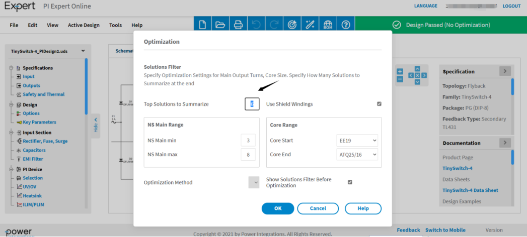
After clicking “OK”, six options will pop up as follows:
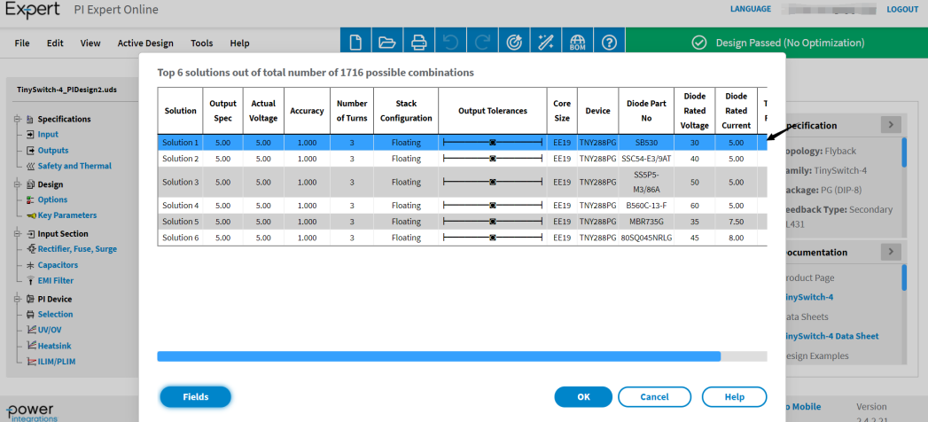
We select the first option and confirm.
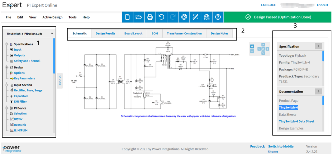
The pop-up interface is relatively simple, and the schematic diagram can be zoomed in and out in real time using the mouse wheel.
The left "1" column is a parameter setting box, such as: input and output voltage modification, transformer design, clamping absorption circuit design, input and output filter circuit, loop compensation design, etc. Users can configure according to their own situation. As shown in the figure below, it is the design modification of the clamping circuit.
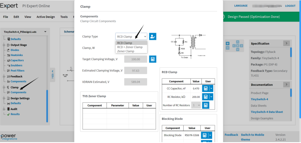
After we click on the clamp circuit, an interface pops up, where users can easily select the absorption method of the clamp circuit. We select the "RCD absorption" method, and the schematic diagram changes quickly, and the pins of the transformer in the schematic diagram are also numbered.
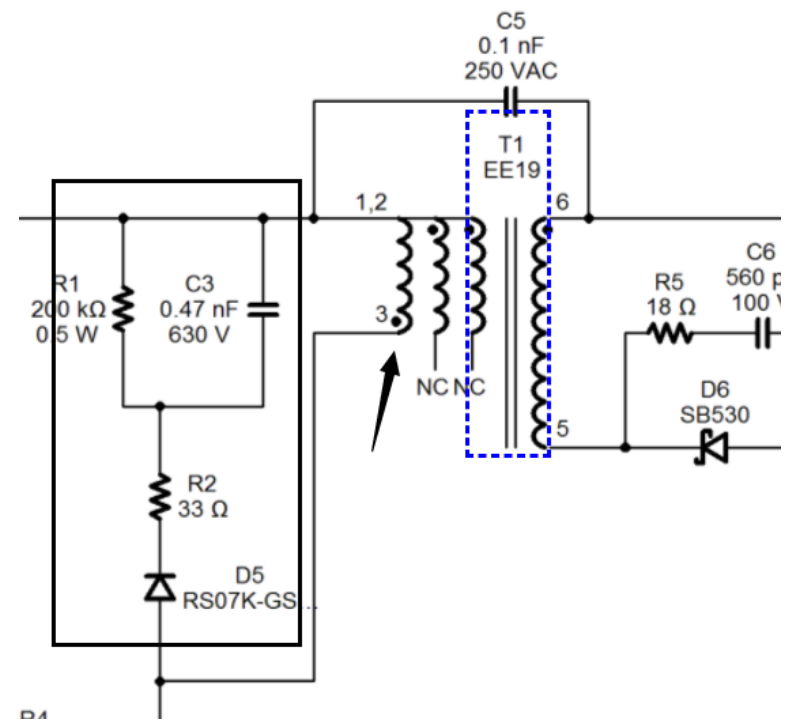
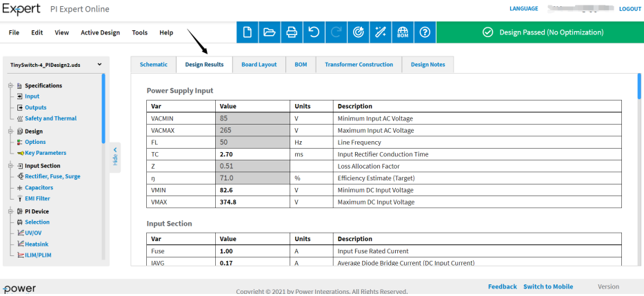
The middle part includes schematic diagram, design results, circuit board layout, BOM, transformer structure and design considerations. The design result output helps users to check and confirm the design parameters.
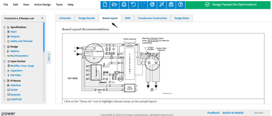
PCB layout minimizes the user's design difficulty and quickly completes the layerout design work.
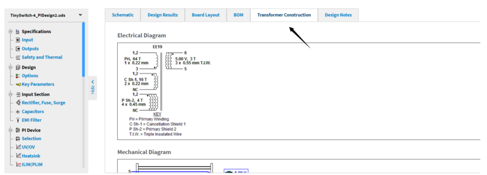
Transformer design includes information such as electrical characteristic schematics, winding structure diagrams, winding instructions, and electrical characteristic test rules.
In addition, on the right side of the schematic, PI also provides reference materials such as data sheets, design examples, and application notes for related devices. There is also a design warning prompt in the upper right corner, which can detect problems in the design in real time. Finally, we click the File drop-down menu to output the design results.
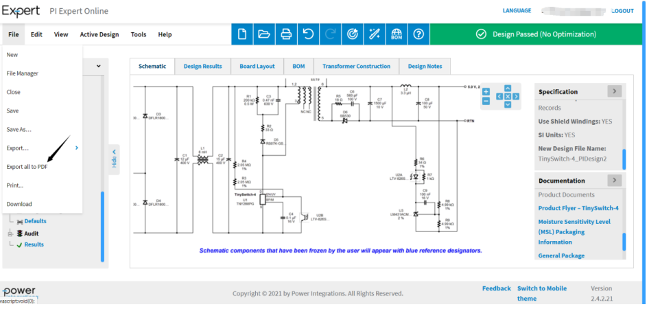
Next, let's experience the PI Xls high-frequency transformer design function. This option is more suitable for users with some experience in power supply design. It is easier to change the relevant parameters in the transformer design, allowing designers to experience the effect of "what you see is what you get" in real-time transformer optimization.
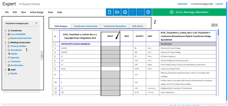
The transformer design page is divided into two parts. The first part on the left is the high-frequency transformer parameter design menu, which can edit the physical parameters of the transformer. The second part on the right is the main part, which mainly adjusts the electrical design of the high-frequency transformer.
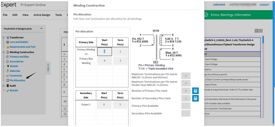
For example, if we select the "Pin Assignment Option", the user can edit the pins of the transformer.
Sometimes, in order to achieve better EMC performance, ordinary designs may not meet our requirements. At this time, we need to add a shielding layer to further improve the characteristics of the high-frequency transformer. We can do this by selecting the "Shielding" option that pops up, checking it and confirming it.
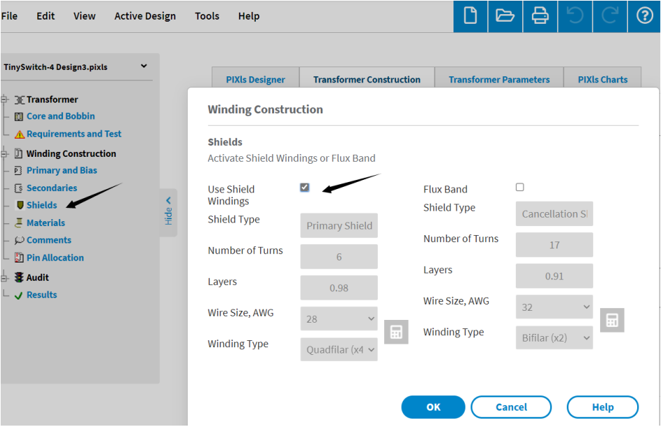
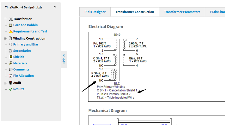
After confirmation, the transformer has two more layers of shielding, which is very beneficial for improving electromagnetic compatibility.
The main part on the right is the transformer electrical parameter design box. The gray part needs to be filled in by the user. If it is not filled in, the system will design according to the default value.
Previous article:Hangyu Power brought high-tech products to the Western Electric Expo
Next article:element14 Significantly Expands Its Cable and Wire Management Solutions Portfolio
Recommended ReadingLatest update time:2024-11-15 19:28


- Popular Resources
- Popular amplifiers
-
 Wireless Sensor Network Technology and Applications (Edited by Mou Si, Yin Hong, and Su Xing)
 -
 Principles and Key Technologies of Lithium-ion Batteries (Edited by Huang Kelong, Wang Zhaoxiang and Liu Suqin)
 -
 Raspberry Pi Development in Action (2nd Edition) ([UK] Simon Monk)
 -
 Electric traction automatic control system Motion control system 5th edition (Ruan Yi, Yang Ying, Chen Boshi)
- MathWorks and NXP Collaborate to Launch Model-Based Design Toolbox for Battery Management Systems
- STMicroelectronics' advanced galvanically isolated gate driver STGAP3S provides flexible protection for IGBTs and SiC MOSFETs
- New diaphragm-free solid-state lithium battery technology is launched: the distance between the positive and negative electrodes is less than 0.000001 meters
- [“Source” Observe the Autumn Series] Application and testing of the next generation of semiconductor gallium oxide device photodetectors
- 采用自主设计封装,绝缘电阻显著提高!ROHM开发出更高电压xEV系统的SiC肖特基势垒二极管
- Will GaN replace SiC? PI's disruptive 1700V InnoMux2 is here to demonstrate
- From Isolation to the Third and a Half Generation: Understanding Naxinwei's Gate Driver IC in One Article
- The appeal of 48 V technology: importance, benefits and key factors in system-level applications
- Important breakthrough in recycling of used lithium-ion batteries
- LED chemical incompatibility test to see which chemicals LEDs can be used with
- Application of ARM9 hardware coprocessor on WinCE embedded motherboard
- What are the key points for selecting rotor flowmeter?
- LM317 high power charger circuit
- A brief analysis of Embest's application and development of embedded medical devices
- Single-phase RC protection circuit
- stm32 PVD programmable voltage monitor
- Introduction and measurement of edge trigger and level trigger of 51 single chip microcomputer
- Improved design of Linux system software shell protection technology
- What to do if the ABB robot protection device stops
- Car key in the left hand, liveness detection radar in the right hand, UWB is imperative for cars!
- After a decade of rapid development, domestic CIS has entered the market
- Aegis Dagger Battery + Thor EM-i Super Hybrid, Geely New Energy has thrown out two "king bombs"
- A brief discussion on functional safety - fault, error, and failure
- In the smart car 2.0 cycle, these core industry chains are facing major opportunities!
- The United States and Japan are developing new batteries. CATL faces challenges? How should China's new energy battery industry respond?
- Murata launches high-precision 6-axis inertial sensor for automobiles
- Ford patents pre-charge alarm to help save costs and respond to emergencies
- New real-time microcontroller system from Texas Instruments enables smarter processing in automotive and industrial applications
- Sandia Labs develops battery failure early warning technology to detect battery failures faster
- Brushless DC Motor
- 8 star products from industry leaders, listed on EDN Hot 100, let’s take a look
- Pimoroni Badger 2040 badge
- What inverter chip should I use for a 200Khz square wave signal?
- Free application: National Technology dual-core, with CAN Bluetooth N32WB452 is here
- Unboxing experience of ST MEMS sensor board (IKS01A3) based on STM32F411RE!
- Smart locks and electric cars are trending on the Internet because the weather in Beijing is too cold!
- 101 Examples of Application Skills of Simulation Technology
- MSP430 common program architecture
- [ESP32-Audio-Kit Audio Development Board Review] 2. Download Audio Firmware


 Wireless Sensor Network Technology and Applications (Edited by Mou Si, Yin Hong, and Su Xing)


 京公网安备 11010802033920号