● 936 soldering station, diagonal pliers, needle-nose pliers, tweezers, lead-free solder, electric screwdriver, soldering oil, handheld multimeter, hand drill and several drill bits, manual tapper and tapping drill bits
● Electric grinder
○ Toggle switch
○ Iron instrument housing
○ 28V100W toroidal transformer
○ Standard 3-port power socket (same as the one on the back of a computer power supply)
○ One LED (preferably green)
○ One 120 ohm 1/4W resistor
○ One 3.5K ohm 1/4W resistor
○ LT1083CT one
○ 5~10K ohm adjustable resistor (3296 type)
○ One SMD radiator
○ Full bridge one
○ One diode 1N4007
○ A computer CPU radiator and fan
○ Tantalum capacitor 35V22UF one
○LM7815 one
○ Some nylon cable ties
Front view
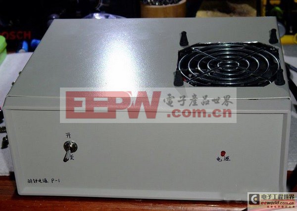
This is a universal metal instrument housing. On the front is a toggle switch and an LED power indicator, which is red (generally speaking, the power indicator should be green, but I only had red, so I used it.). A hole was drilled on it with an electric grinder to install a ball bearing cooling fan. It is not fixed with screws, but shock-absorbing rubber is used to reduce the vibration sound of the fan. Tail diagram
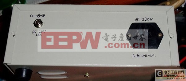
This is the tail, the power cord has a universal 3-pin socket, the same as the power cord on the computer case, which is easy to replace. The power output port uses a 5.5MM universal output terminal, the inner core is positive and the outer shell is negative.
Internal diagram
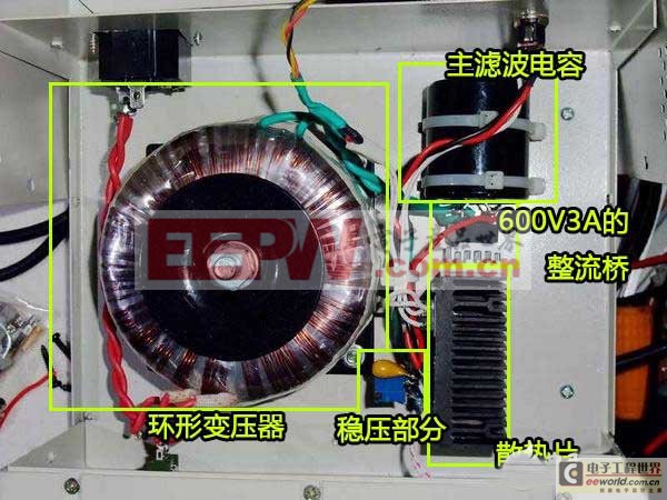
The biggest thing is a custom-made toroidal transformer, which has the advantages of small size, high power, low magnetic leakage, and a higher price. The parameters are 28V 100W, which is equivalent to 28V3.5A. The black part on the right fixed with a tie is the main filter capacitor, with a withstand voltage of 63V10000UF.
Some people may ask, why is 63V used here when the previous voltage is 28V? In fact, the previous voltage value is AC voltage. After rectification, the maximum voltage fluctuation is 28V*1.414=39.592V. Generally speaking, the voltage of electrolytic capacitors is divided into 25V-35V-50V-63V. In this case, choosing 50V withstand voltage is the most economical and practical. However, netizens may not always have capacitors with suitable voltages, so they increase the withstand voltage value of the selected capacitors. Although the cost will increase if components are used in excess, their reliability and life will be much longer.
The thing with a small heat sink welded on its foot is a 600V3A rectifier bridge, which is equivalent to 4 diodes bridged. A heat sink is added because the current passing through is relatively large. If the chassis shell is made of aluminum, you can also directly apply thermal conductive silicone grease and lock it directly on the shell to dissipate heat, which will lower the temperature.
x; padding: 0px; word-wrap: break-word; text-indent: 2em; line-height: 24px; color: rgb(62, 62, 62); font-family: Tahoma, Arial, sans-serif; font-size: 14px; text-align: justify; ">The one with a black heat sink is the main circuit of the voltage-stabilized power supply . Of course, this heat sink is a bit small. If you like fanless, the volume of the radiator should be about 4 to 5 times larger.
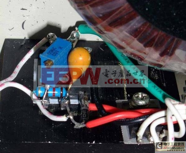
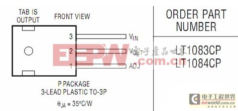
Because we need to output a relatively large current of about 2A, and keep the cost as low as possible while ensuring the simplicity and performance of the circuit, we chose the LT1083CT three-terminal adjustable voltage regulator from LT Company of the United States .
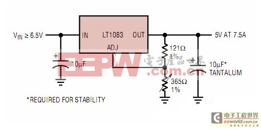
The circuit is very simple, and its basic circuit needs to be slightly modified. The input voltage is about 40V DC, the capacity of the input aluminum foil capacitor is 10000UF, the adjustable resistance of the ADJ end uses a 10K ohm 3296 precision adjustable potentiometer, and the output uses a 35V22UF tantalum capacitor, because the impedance of the tantalum capacitor is quite small and the high-frequency characteristics are also quite good, which can be equivalent to the output performance of a 1000UF ordinary electrolytic capacitor, or even better.
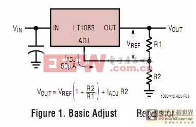
The output voltage of the three-terminal adjustable regulator is determined by the ratio of R1 and R2. Usually the value of R1 is 100 ohms to 120 ohms, and the output voltage is always less than the input voltage.
Let's look at its output characteristics. The current power supply is about 40V DC, and the output is 24V DC, with a voltage difference of 16V. In fact, I should have lowered the voltage difference, because the higher the voltage difference, the greater the heat generated by the voltage regulator. This is not a good thing. When I customized the transformer, I didn't calculate the parameters well, and I just quoted 28V.

A hole was opened on the top, and an 8015 11-blade silent fan was installed. It is from NMB (Japan Meipei) and is powered by 24V DC. In order to reduce noise, an LM7815 was installed to reduce the power supply voltage, reduce the speed and noise, and isolate some fan interference. Because the metal backplane of the three-terminal regulator is usually connected to its voltage output pin (not absolutely), insulators and insulating heat dissipation silicone pads are used to insulate and conduct heat from the radiator to prevent short circuits. Test
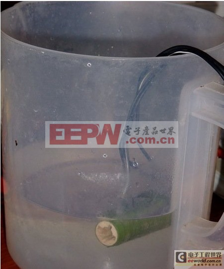
Finally, the full power test is done. According to the actual usage, the current is about 2A, and then gradually decreases to below 1A. Then, just connect a power resistor directly to the 24V end. The resistor used is a 25W 10 ohm ceramic core wound power resistor. The current on the resistor is 24V/10 ohm = 2.4A, and the actual power consumption is 24*2.4=57.6W, which is far more than the resistance power. So let's water cool it, just throw a cup of water. After working for an hour, the water temperature is hot, and the temperature of the internal regulator and rectifier bridge is acceptable. Basically, the power supply is successful.
However, the power supply for self-use cannot be so simple. For example, a voltmeter can be connected to the output port and an ammeter can be connected in series to monitor the actual voltage value and current consumption; the 3296 potentiometer can be replaced with a larger multi-turn adjustable potentiometer installed on the panel, so that the output voltage can be adjusted. For this circuit, the output voltage can be infinitely adjustable within the range of 1.25V~35V. The output can even be reduced to 0V with a change. If the current demand is not large, you can replace it with a cheaper three-terminal regulator, such as LM317T, which has the same output voltage range as LT1083CT, a maximum current of 1.5A (needs proper heat dissipation), and the pin definition is the same. You can also make a battery charger based on its voltage regulation performance. It can even be used as an audio amplifier.
Previous article:Technology: Engineers share the design of series-adjusted voltage-stabilized power supply circuit
Next article:Analysis of EMI Causes and Anti-interference Measures Based on Switching Power Supply
- Popular Resources
- Popular amplifiers
- MathWorks and NXP Collaborate to Launch Model-Based Design Toolbox for Battery Management Systems
- STMicroelectronics' advanced galvanically isolated gate driver STGAP3S provides flexible protection for IGBTs and SiC MOSFETs
- New diaphragm-free solid-state lithium battery technology is launched: the distance between the positive and negative electrodes is less than 0.000001 meters
- [“Source” Observe the Autumn Series] Application and testing of the next generation of semiconductor gallium oxide device photodetectors
- 采用自主设计封装,绝缘电阻显著提高!ROHM开发出更高电压xEV系统的SiC肖特基势垒二极管
- Will GaN replace SiC? PI's disruptive 1700V InnoMux2 is here to demonstrate
- From Isolation to the Third and a Half Generation: Understanding Naxinwei's Gate Driver IC in One Article
- The appeal of 48 V technology: importance, benefits and key factors in system-level applications
- Important breakthrough in recycling of used lithium-ion batteries
- LED chemical incompatibility test to see which chemicals LEDs can be used with
- Application of ARM9 hardware coprocessor on WinCE embedded motherboard
- What are the key points for selecting rotor flowmeter?
- LM317 high power charger circuit
- A brief analysis of Embest's application and development of embedded medical devices
- Single-phase RC protection circuit
- stm32 PVD programmable voltage monitor
- Introduction and measurement of edge trigger and level trigger of 51 single chip microcomputer
- Improved design of Linux system software shell protection technology
- What to do if the ABB robot protection device stops
- How Lucid is overtaking Tesla with smaller motors
- Wi-Fi 8 specification is on the way: 2.4/5/6GHz triple-band operation
- Wi-Fi 8 specification is on the way: 2.4/5/6GHz triple-band operation
- Vietnam's chip packaging and testing business is growing, and supply-side fragmentation is splitting the market
- Vietnam's chip packaging and testing business is growing, and supply-side fragmentation is splitting the market
- Three steps to govern hybrid multicloud environments
- Three steps to govern hybrid multicloud environments
- Microchip Accelerates Real-Time Edge AI Deployment with NVIDIA Holoscan Platform
- Microchip Accelerates Real-Time Edge AI Deployment with NVIDIA Holoscan Platform
- Melexis launches ultra-low power automotive contactless micro-power switch chip
- EEWORLD University Hall----What can universal fast charging bring?
- Complete learning manual for using RT-Thread on RISC-V (based on Longan development board)
- How does Tbox protect itself to ensure data security? What good methods can you recommend?
- The amount of heat required to heat water
- High-efficiency integrated power supplies from Texas Instruments
- Encoder Problems
- When defining global variables in Keil, if an initial value is assigned, will the value of the variable remain the same every time the power is turned on again?
- Are the emoticons that were commonly used in the forum gone?
- Recruiting senior electronic engineers
- IMP34DT05 data sheet, package and other information

 ARA2000S12


 京公网安备 11010802033920号