1. Introduction
In recent years, with the continuous development of semiconductor technology, LED, as a new type of light source with low power supply voltage, low power consumption, long life and no radiation, has been increasingly applied. It is expected to completely replace traditional incandescent and fluorescent bulbs and become a key light source for solid-state lighting. Many solid-state lighting applications often use intelligent control circuit systems to drive LEDs to perform various functions and tasks. For example, brightness adjustment is one of the tasks of the control circuit system to ensure that the current flowing through the LED is not affected by power supply voltage fluctuations and remains constant, so that the brightness of the LED does not change significantly. Brightness adjustment involves current adjustment and dimming control. Another task of the control circuit system is failure identification. Because LEDs have a strong temperature correlation and most failures are related to temperature, the control circuit system should be able to perform temperature compensation. In addition, it is also necessary to select hardware to adapt to the drive of different brightness LED combinations . The PIC microcontroller, which can integrate all necessary hardware functions on a chip, is very suitable for LED drive control circuits due to its low price, clock frequency of up to 20MHz, extremely low power consumption and wide operating temperature range. This article discusses some considerations for designing LED drive control circuits using PIC microcontrollers as control units .
PIC Microcontroller
PIC stands for Programmable Interrupt Controller, a type of multifunctional integrated device that can be erased and rewritten using electricity or ultraviolet light. Figure 1 is a typical functional block diagram of a PIC microcontroller from Microchip.

The PIC microcontroller is used as the core of the LED drive control circuit system. Several complete modules and some pins are set as analog inputs. The analog voltage is converted to digital quantity through the A/D module. The converted signal is sent directly to the A/D module by software selection. The constant reference voltage of the module can be applied externally through the input pin or through the internal reference voltage module. If the latter is adopted, the power supply voltage of the PIC should be kept constant by the voltage regulator. The controller programming does not require a lot of hardware. Simple programming devices can be established by searching for examples on www.ic-prog.com. The software that generates executable assembly programs in the controller can be downloaded free of charge. PIC recommends using a C compiler that is easy to handle and allows changes. The program can adopt a modular design idea. Set up functional module subroutines with the main program as the core to simplify the design structure. During the operation, the main program calls each functional module subroutine and performs loop control to meet the requirements.
3. LED Configuration
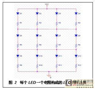
When designing an LED driver circuit, the configuration of the LED must be considered. In principle, there are three possible configurations for LEDs: the entire circuit is connected in an array with resistors, each LED is connected in series with a resistor, or connected in an array with resistors. Figure 2 shows an LED array connection with one resistor per LED. In the figure, each LED has its own resistor, which can be used as a reference resistor to adjust the diode current.
For example, if an LED fails, the remaining LEDs in the non-series connection will continue to operate, but since the total current can be distributed among the remaining three paths, the failure will cause an increase in the current in the parallel diodes, causing an uneven distribution of brightness. However, the loss of brightness can be fundamentally compensated by the increase in current of the remaining LEDs in the same path as the failed device.
4. Driver control function
① Dimming
Dimming is the most basic function of driver control, and different LED brightness levels are generated through dimming. Using pulse width modulation (PWM) is a simple way to solve dimming. The PWM signal is actually the on-off switching of the DC voltage in a cycle, so the PWM signal can be easily set and controlled using the built-in PWM module of the microprocessor. If it is inconvenient to maintain the cycle, the brightness can be adjusted by the duration of the pulse, that is, the duty cycle D. The advantage of using a PWM signal is that the peak current can be kept constant, thereby preventing negative effects such as wavelength shift in InGaN devices caused by the increase in peak current.
② Current adjustment
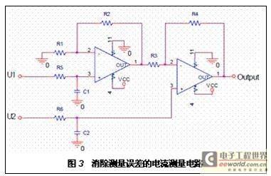
The second function of the driver control is to keep the brightness of the LED constant. To ensure constant brightness of the LED, the current flowing through the LED must be constant. This requires that the current flowing through each individual LED is determined. To determine the current flowing through the diode, a series resistor is used for each diode. By measuring the voltage across the resistor, the current flowing through the resistor can be measured, and therefore the current flowing through the LED can be determined. The voltage measurement is performed by the A/D module in the PIC, which can measure voltages up to 5V and can be compared with a constant reference voltage. However, the A/D module cannot be directly connected across the series resistor, partly because the voltage level can be much higher than 5V, and partly because the PWM signal must first be converted into a DC signal. The double measurement error will be generated by the two measurements and the subsequent subtraction. It is recommended to use the current measurement circuit shown in Figure 3 to eliminate the double measurement error problem.
When using this circuit, any positive input voltage is connected to U1 and any negative input voltage is connected to U2. In the figure, the U1 and U2 signals are converted to DC signals by RC elements and then connected to the op amp. The op amp can be configured as a subtractor using various resistors. For this circuit, the DC voltage of U1 will be subtracted from that of U2, and the difference is measured by the A/D module. This allows the controller to react to changes in current. Since the operational amplifier has a very high input impedance, the system will not be affected by the measurement circuit.
③ Temperature measurement
However, due to the influence of temperature, the brightness will change even if the current remains unchanged. Figure 4 shows the relationship between brightness and temperature:
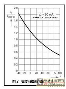
In order to maintain constant brightness over the entire temperature extremes, temperature compensation must be used. Considering that the ambient temperature should be measured as cheaply as possible, the compensation accuracy is not required to be high for the diode, and a tolerance of 5°C is sufficient. Two possible temperature measurement methods are given below:
Temperature measurement using temperature-dependent resistors
First, select a temperature-dependent resistor and connect it in series with a temperature-independent resistor. By measuring the voltage through the A/D module, the temperature can be determined and the controller can respond accordingly. The disadvantage of this method is that the response curve of the resistor must be saved in the form of a numerical table in the PIC.
Measuring Temperature Using a Threshold Timer
This method uses the blocking effect of the PIC threshold timer module. The threshold timer module consists of an 8-bit timer regulated by an internal RC oscillator. Usually, the timer runs in the background and is often reset by the microprocessor. If the controller fails or falls into an infinite loop, it can return to the set state. However, the RC oscillator used should be temperature-dependent. If an external temperature-compensated clock generator is used, the temperature can be determined by comparing the two clock generators. Measuring temperature with a threshold timer does not require external components, but the PIC manufacturer cannot guarantee the temperature dependency of the threshold timer.
④ Fault identification
Of course, if the LED is not working, the brightness adjustment is useless. Here is a method to detect the contribution of a single LED in the array to the total fault. Fault identification can use the circuit used to detect current. The total failure of the LED is to cause the channel to be interrupted, so that no current flows through the series resistor. Due to the expensive component cost and the limitations of the equipment involved, it is naturally impossible to add a current detection circuit to each diode. This problem is solved here by using a multiplexer switch that allows each diode to be selected and connected to the measurement circuit. Figure 5 shows a description of the fault identification technique using a multiplexer switch for a circuit containing three diodes.
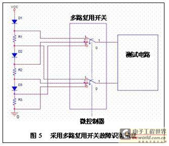
The multiplexer can be digitally controlled by a microcontroller. To determine the current flowing through the current regulating diode and to aid in fault identification, each LED is labeled with an address that can be selected by the PIC.
⑤ Adjustment of different brightness groups
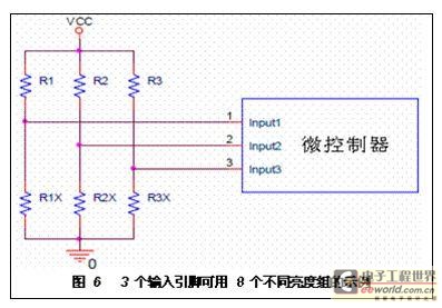
An additional option is a driver circuit system consisting of adjustable brightness groups. For many LEDs, care must be taken to divide the same type of LED into groups with different brightness. The use of different brightness groups results in different brightness for the same current flowing through the LED. The brightness can be adjusted using a PWM signal. Programmable input/output pins provide an adjustment method without reconfiguring the controller. Since each independent brightness group is selected by a number, there must be enough input pins to distinguish the brightness groups of all digital signs. For example, with 3 input pins, 2 3 = 8 brightness groups can be distinguished. Then, according to the configuration of the input pin (high or low), the number at the controller input can be specified to select the corresponding brightness group, and its brightness can therefore be adjusted. Figure 6 shows an example of 8 different brightness groups available for 3 input pins. Depending on the value of resistors R1X - R3X, the input of the microcontroller will receive a high level signal greater than 4V or a low level signal less than 1V, thereby selecting the corresponding brightness group.
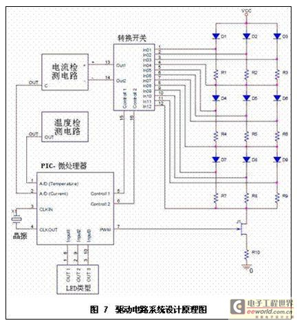
Based on the above considerations, the design schematic diagram of the drive circuit system shown in Figure 7 can be obtained:
V. Conclusion
PIC microcontroller can integrate many necessary hardware functions on a single chip, which is very suitable for LED intelligent control drive system. This article discusses various considerations for designing LED drive control circuit with PIC microcontroller as control unit, and proposes design schematic diagram. Hopefully, it can provide some reference information for LED to completely replace traditional incandescent lamps and fluorescent lamps.
Previous article:Green LED Driver Reference Design Based on TRIAC Dimming
Next article:Design of LED drive circuit without electrolytic capacitor
- Popular Resources
- Popular amplifiers
- MathWorks and NXP Collaborate to Launch Model-Based Design Toolbox for Battery Management Systems
- STMicroelectronics' advanced galvanically isolated gate driver STGAP3S provides flexible protection for IGBTs and SiC MOSFETs
- New diaphragm-free solid-state lithium battery technology is launched: the distance between the positive and negative electrodes is less than 0.000001 meters
- [“Source” Observe the Autumn Series] Application and testing of the next generation of semiconductor gallium oxide device photodetectors
- 采用自主设计封装,绝缘电阻显著提高!ROHM开发出更高电压xEV系统的SiC肖特基势垒二极管
- Will GaN replace SiC? PI's disruptive 1700V InnoMux2 is here to demonstrate
- From Isolation to the Third and a Half Generation: Understanding Naxinwei's Gate Driver IC in One Article
- The appeal of 48 V technology: importance, benefits and key factors in system-level applications
- Important breakthrough in recycling of used lithium-ion batteries
- LED chemical incompatibility test to see which chemicals LEDs can be used with
- Application of ARM9 hardware coprocessor on WinCE embedded motherboard
- What are the key points for selecting rotor flowmeter?
- LM317 high power charger circuit
- A brief analysis of Embest's application and development of embedded medical devices
- Single-phase RC protection circuit
- stm32 PVD programmable voltage monitor
- Introduction and measurement of edge trigger and level trigger of 51 single chip microcomputer
- Improved design of Linux system software shell protection technology
- What to do if the ABB robot protection device stops
- CGD and Qorvo to jointly revolutionize motor control solutions
- CGD and Qorvo to jointly revolutionize motor control solutions
- Keysight Technologies FieldFox handheld analyzer with VDI spread spectrum module to achieve millimeter wave analysis function
- Infineon's PASCO2V15 XENSIV PAS CO2 5V Sensor Now Available at Mouser for Accurate CO2 Level Measurement
- Advanced gameplay, Harting takes your PCB board connection to a new level!
- Advanced gameplay, Harting takes your PCB board connection to a new level!
- A new chapter in Great Wall Motors R&D: solid-state battery technology leads the future
- Naxin Micro provides full-scenario GaN driver IC solutions
- Interpreting Huawei’s new solid-state battery patent, will it challenge CATL in 2030?
- Are pure electric/plug-in hybrid vehicles going crazy? A Chinese company has launched the world's first -40℃ dischargeable hybrid battery that is not afraid of cold
- Can the comment statement in C language be written in the IF judgment condition in KEIL5?
- How to handle the error in calling the ti.osal.ae674 library when porting the FATFS routine of pdk_omapl138?
- Problems with functionality after reset
- ZTE's 7nm chip mass production still needs time to catch up with high-end chip track
- 【Qinheng RISC-V core CH582】Timer PWM drive servo
- Selection and use of bypass capacitors
- CircuitPython Holiday Wreath
- Application and advantages of mica capacitors
- First Battlefield
- Infrared remote control LED dot matrix

 NJM4559E-(TE2)


 京公网安备 11010802033920号