MDIO is a transmission protocol of an Ethernet controller, which is widely used for data communication between Ethernet controllers and PHY. Next, let us take a closer look at the MDIO protocol.
MDIO (Management Data Input/Output) is an Ethernet industry standard defined by IEEE802.3. It carries the heavy responsibility of communication between the MAC layer and the physical layer. The MDIO interface includes two signal lines: MDC and MDIO. The MAC layer chip (or other control chip) can access the registers of the physical layer chip through them, and control and manage the physical chip through these registers.
MDC: The clock of the management interface is a non-periodic signal with a minimum period of 400ns, a minimum positive level time and a minimum negative level time of 160ns, and no maximum positive and negative level time restrictions.
MDIO: It is a bidirectional data line used to transmit MAC layer control information and physical layer status information. It is synchronized with the MDC clock and is valid on the rising edge of the MDC.
Now let's take a look at the performance of MDIO on the ZDS2024 plus oscilloscope:
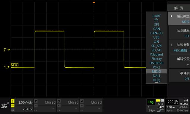
Open the Decode menu, we can see that MDIO has been added.


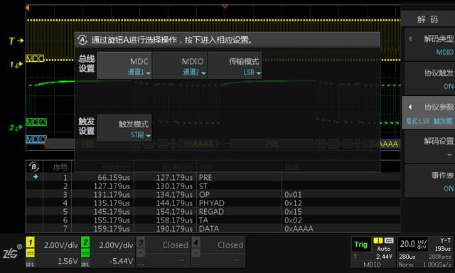
Select the MDIO protocol, and you can see that the MDIO parameter settings are very simple. You only need to set the MDC, MDIO channel, and data transmission mode.

Connect the probe to the MDIO bus to capture data. Because the baud rate of MDIO transmission is high, we need to set the probe attenuation ratio to x10 to reduce waveform distortion. We can see that MDIO decoding has started and the results are accurate.

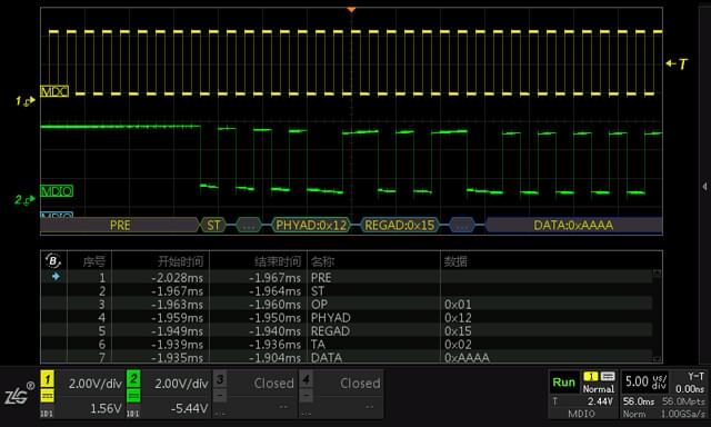
Here, we can see from the event table that the decoded PHYAD of this frame is 0x12, so can we capture this frame from the data torrent? In fact, we can. The MDIO protocol not only implements the decoding function, but also has a powerful trigger function. We can capture this frame separately through the MDIO protocol trigger.
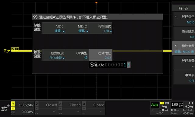
We first set the trigger parameters, as shown in the figure below, we set the OP type to: read, and the chip address to: 0x12.

The access signal triggers an immediate response, and the trigger point stabilizes after the PHYAD segment with a value of 0x12. The specific frame is captured successfully!

In addition to PHYAD trigger, MDIO trigger can also be triggered according to ST, OP, REGAD and DATA segments, which is very practical.
So far, the demonstration of the MDIO protocol has come to an end. Do you need to use the MDIO bus in your development? Are you eager to try to spy on various problems that may occur on the bus? ZDS2022 plus and ZDS2024 plus currently support the MDIO protocol. Upgrade your oscilloscope and add MDIO to it.
Appendix: MDIO frame structure
A standard MDIO frame includes PRE, ST, OP, PHYAD, PEGAD, TA, and DATA segments, as shown in the following figure.

PRE: Frame prefix field, which is 32 consecutive "1" bits. This frame prefix field is not necessary. The MDIO operation of some physical layer chips does not have this field.
OP: frame operation code, bit "10" indicates that this frame is a read operation frame, and bit "01" indicates that this frame is a write operation frame.
PHYAD: The address of the physical layer chip, 5 bits. Each chip compares its own address with these 5 bits. If they match, it responds to the subsequent operations. If they do not match, it ignores the subsequent operations.
REGAD: Used to select the address of a register among the 32 registers of the physical layer chip.
TA: state transition domain, if it is a read operation, the MDIO is in high impedance state in the first bit, and the physical layer chip sets MDIO to "0" in the second bit. If it is a write operation, the MDIO is still controlled by the MAC layer chip, which continuously outputs two bits of "10".
DATA: The data field of the frame register, 16 bits. If it is a read operation, it is the data sent from the physical layer to the MAC layer. If it is a write operation, it is the data sent from the MAC layer to the physical layer.
IDLE: The idle state after the frame ends. At this time, MDIO is passively driven and in a high-impedance state, but a pull-up resistor is generally used to keep it at a high level, that is, the MDIO pin requires a pull-up resistor.
Previous article:Application of digital filtering function in circuit noise interference test
Next article:About the Noise Floor of Oscilloscopes
- Popular Resources
- Popular amplifiers
- Seizing the Opportunities in the Chinese Application Market: NI's Challenges and Answers
- Tektronix Launches Breakthrough Power Measurement Tools to Accelerate Innovation as Global Electrification Accelerates
- Not all oscilloscopes are created equal: Why ADCs and low noise floor matter
- Enable TekHSI high-speed interface function to accelerate the remote transmission of waveform data
- How to measure the quality of soft start thyristor
- How to use a multimeter to judge whether a soft starter is good or bad
- What are the advantages and disadvantages of non-contact temperature sensors?
- In what situations are non-contact temperature sensors widely used?
- How non-contact temperature sensors measure internal temperature
- LED chemical incompatibility test to see which chemicals LEDs can be used with
- Application of ARM9 hardware coprocessor on WinCE embedded motherboard
- What are the key points for selecting rotor flowmeter?
- LM317 high power charger circuit
- A brief analysis of Embest's application and development of embedded medical devices
- Single-phase RC protection circuit
- stm32 PVD programmable voltage monitor
- Introduction and measurement of edge trigger and level trigger of 51 single chip microcomputer
- Improved design of Linux system software shell protection technology
- What to do if the ABB robot protection device stops
- CGD and Qorvo to jointly revolutionize motor control solutions
- CGD and Qorvo to jointly revolutionize motor control solutions
- Keysight Technologies FieldFox handheld analyzer with VDI spread spectrum module to achieve millimeter wave analysis function
- Infineon's PASCO2V15 XENSIV PAS CO2 5V Sensor Now Available at Mouser for Accurate CO2 Level Measurement
- Advanced gameplay, Harting takes your PCB board connection to a new level!
- Advanced gameplay, Harting takes your PCB board connection to a new level!
- A new chapter in Great Wall Motors R&D: solid-state battery technology leads the future
- Naxin Micro provides full-scenario GaN driver IC solutions
- Interpreting Huawei’s new solid-state battery patent, will it challenge CATL in 2030?
- Are pure electric/plug-in hybrid vehicles going crazy? A Chinese company has launched the world's first -40℃ dischargeable hybrid battery that is not afraid of cold
- Maxwell's Equations 3D Animation
- Some issues with ob6572 chip
- [RVB2601 creative application development] hello world
- MicroPython further improves the file system
- Do you use cmake a lot in practice? Please share your thoughts on using it, having used it, or thinking of using it.
- EEWORLD University Hall----Industrial Robot Seminar
- TMS320C62x Boot Mode
- GPIO block diagram of C6000 series DSP
- [New version of Zhongke Bluexun AB32VG1 RISC-V development board] - 0: Unboxing post - At this point it surpasses "UNO"
- ADCPro and DXP FAQ

 LT1801CS8#PBF


 京公网安备 11010802033920号