As power converters become more common, electronic device manufacturers are demanding new features and functions from their power systems, such as lower input and output voltages, higher currents, and faster transient response.
To meet these demands, switching power supply designers began to adopt synchronous rectification (SR) technology in the late 1990s - using MOSFETs to replace the rectification function commonly performed by diodes. SR improves efficiency, thermal performance, power density, manufacturability, and reliability, and can reduce the power system cost of the entire system. This article will introduce the advantages of SR and discuss the challenges encountered in its implementation. Disadvantages of Diode Rectification
Figure
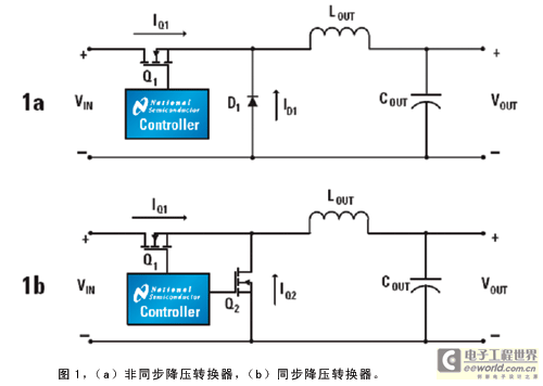
1 is a schematic diagram of a nonsynchronous and synchronous buck converter. A nonsynchronous buck converter uses a FET and a Schottky diode as the switching device (Figure 1a). When the FET is turned on, energy is transferred to the output inductor and the load. When the FET is turned off, the current in the inductor flows through the Schottky diode. If the load current is higher than half of the ripple current of the output inductor, the converter operates in continuous conduction mode. The Schottky diode is selected based on its forward voltage drop and reverse leakage current characteristics. However, when the output voltage is reduced, the forward voltage of the diode becomes important, which will reduce the efficiency of the converter. Physical limitations make it difficult to reduce the forward voltage drop of the diode below 0.3V. In contrast, the on-resistance RDS(ON) of the MOSFET can be reduced by increasing the size of the silicon die or connecting discrete devices in parallel. Therefore, using a MOSFET to replace the diode can achieve a much smaller voltage drop than a diode at a given current. 
This makes SR very attractive, especially in applications that are sensitive to efficiency, converter size and thermal performance, such as portable or handheld devices. MOSFET manufacturers continue to introduce new MOSFET technologies with lower RDS(ON) and total gate charge (QG), which makes it easier to implement SR in power converter designs.
What is synchronous rectification?
For example, in a synchronous buck converter, efficiency can be improved by replacing the Schottky diode with two low-side MOSFETs (Figure 1b). The two MOSFETs must be driven in complementary mode with a small dead time between their conduction intervals to avoid simultaneous conduction. Synchronous FETs operate in the third quadrant because current flows from source to drain. In contrast to its non-synchronous counterpart, a synchronous buck converter always operates in continuous conduction, even at no load.
During the dead time, the inductor current flows through the body diode of the low-side FET. This body diode usually has very slow reverse recovery characteristics, which reduces the efficiency of the converter. A Schottky diode can be placed in parallel with the low-side FET to bypass the body diode and prevent it from affecting the performance of the converter. The added Schottky diode can have a much lower current rating than the diode in the non-synchronous buck converter because it only conducts during the short dead time (usually less than a few percent of the switching period) when both FETs are off.
Benefits of Synchronous Rectification
The benefits of using SR in high-performance, high-power converters are higher efficiency, lower power dissipation, better thermal performance, and the inherent ideal current sharing characteristics when synchronous FETs are connected in parallel, and improved manufacturing yield despite the use of automated assembly processes (higher reliability). As mentioned above, several MOSFETs can be connected in parallel to handle higher output currents.
Since the effective RDS(ON) in this case is inversely proportional to the number of devices connected in parallel, the conduction losses are reduced. Likewise, RDS(ON) has a positive temperature coefficient, so the FETs will share the current equally, helping to optimize the heat distribution between the SR devices, which will improve the ability of the device and PCB to dissipate heat, directly improving the thermal performance of the design. Other potential benefits of SR include smaller form factor, open frame structure, higher ambient operating temperature, and higher power density.
Design tradeoffs of synchronous rectifier converters
In low-voltage applications, designers usually increase the switching frequency to reduce the size of the output inductor and capacitor, thereby minimizing the size of the converter and reducing the output ripple voltage. If multiple FETs are connected in parallel, such an increase in frequency will also increase the gate drive and switching losses, so design tradeoffs must be made based on the specific application. For example, in a high input voltage, low output voltage synchronous buck converter, because the operating condition is that the high-side FET has a lower RMS current than the low-side FET, the high-side FET should be selected with a device with low QG and high RDS(ON). For this device, reducing switching losses is more important than conduction losses. In contrast, the low-side FET carries a larger RMS current, so RDS(ON) should be as low as possible. [page]
Choosing a controller with stronger drive capability in a synchronous converter will reduce switching losses by minimizing the time it takes the FETs to switch on and off. However, faster rise and fall times can generate high-frequency noise that can cause system noise and EMI problems.
Synchronous Rectification Converter Drive
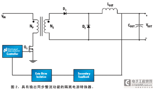
in Isolated TopologiesPower converters using isolated topologies are used in systems that require isolation between system grounds. Such systems include distributed bus architectures, Power over Ethernet systems, and wireless base stations (Figure 2). 
Using SRs in isolated converters can greatly improve their performance. All isolated topologies, including forward, flyback, push-pull, half-bridge, and full-bridge (current and voltage feedback) can perform synchronous rectification. However, providing adequate and timely gate drive signals from the SRs in each topology presents its own challenges.
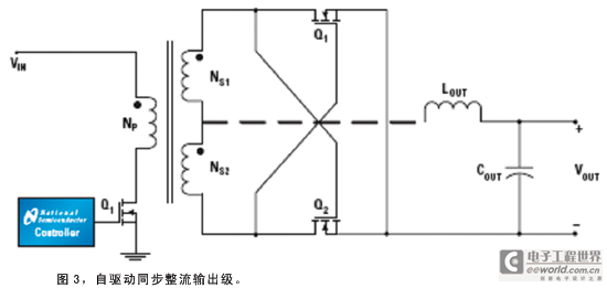
There are basically two approaches to driving the secondary FETs in isolated topologies: self-driven gate signals derived directly from the secondary transformer windings and controlled drive gate signals derived from a PWM controller or some other primary reference signal. These drivers can be implemented in several different ways for a given application. Designers should choose the simplest solution that meets the performance requirements.
The self-driven scheme is the simplest and most direct SR drive scheme (Figure 3), suitable for topologies where the transformer voltage is not zero for any period of time. Two SR FETs can replace the output rectifier diodes, and the voltage generated by the secondary winding drives the gate of the SR. In most cases, the same topology can achieve higher or lower output voltages by using different transformer turns ratios (NP: NS1: NS2) and properly selecting SR FETs.
Previous article:Testing method for thickness of boron-doped p+-Si epitaxial layer
Next article:Compensating and measuring the control loop of a high-power LED driver
- Popular Resources
- Popular amplifiers
- Seizing the Opportunities in the Chinese Application Market: NI's Challenges and Answers
- Tektronix Launches Breakthrough Power Measurement Tools to Accelerate Innovation as Global Electrification Accelerates
- Not all oscilloscopes are created equal: Why ADCs and low noise floor matter
- Enable TekHSI high-speed interface function to accelerate the remote transmission of waveform data
- How to measure the quality of soft start thyristor
- How to use a multimeter to judge whether a soft starter is good or bad
- What are the advantages and disadvantages of non-contact temperature sensors?
- In what situations are non-contact temperature sensors widely used?
- How non-contact temperature sensors measure internal temperature
- LED chemical incompatibility test to see which chemicals LEDs can be used with
- Application of ARM9 hardware coprocessor on WinCE embedded motherboard
- What are the key points for selecting rotor flowmeter?
- LM317 high power charger circuit
- A brief analysis of Embest's application and development of embedded medical devices
- Single-phase RC protection circuit
- stm32 PVD programmable voltage monitor
- Introduction and measurement of edge trigger and level trigger of 51 single chip microcomputer
- Improved design of Linux system software shell protection technology
- What to do if the ABB robot protection device stops
- CGD and Qorvo to jointly revolutionize motor control solutions
- CGD and Qorvo to jointly revolutionize motor control solutions
- Keysight Technologies FieldFox handheld analyzer with VDI spread spectrum module to achieve millimeter wave analysis function
- Infineon's PASCO2V15 XENSIV PAS CO2 5V Sensor Now Available at Mouser for Accurate CO2 Level Measurement
- Advanced gameplay, Harting takes your PCB board connection to a new level!
- Advanced gameplay, Harting takes your PCB board connection to a new level!
- A new chapter in Great Wall Motors R&D: solid-state battery technology leads the future
- Naxin Micro provides full-scenario GaN driver IC solutions
- Interpreting Huawei’s new solid-state battery patent, will it challenge CATL in 2030?
- Are pure electric/plug-in hybrid vehicles going crazy? A Chinese company has launched the world's first -40℃ dischargeable hybrid battery that is not afraid of cold
- Summary of DSP's real clock system--Explained with TI's DSP TMS320F2812 as an example
- E840-DTU device unresponsive problem
- Is it better to first increase the voltage to 5V and then decrease it to 3.3V when using a 3.7V lithium battery? Or is it better to first decrease it to 3.3V and then increase it to 5V?
- Download the Pomona Connectors catalogue and win a Xiaomi Mosquito Repellent!
- Are smaller components better?
- Anyone have any ADS simulation tutorials to share?
- The Xiaomi IoT module wifi version only costs 9.99 yuan. What would you most like to use it for?
- EEWORLD University ---- EDDP Motor Control Demonstration Platform Usage Guide
- SILICON LABS PG22-DK2503A EFM32PG22 Development Kit Unboxing Review
- Parsing STM32 library functions.pdf

 HCMP96870SIJ/A


 京公网安备 11010802033920号