How Inductors Work
Source: InternetPublisher:抄写员 Keywords: Power supply other power circuits Updated: 2021/01/17
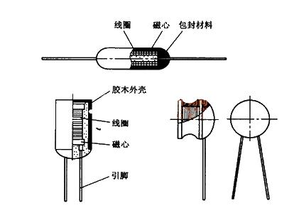
copper coil
Inductance is the ratio of the magnetic flux in the wire to the current that produces this magnetic flux when an alternating current flows through the wire. When DC current passes through the inductor, only fixed magnetic lines of force appear around it, which do not change with time;

However, when an alternating current passes through the coil, magnetic lines of force that change with time will appear around it. According to the analysis of Faraday's law of electromagnetic induction - magnetism generates electricity, the changing magnetic field lines will generate an induced electric potential at both ends of the coil. This induced electric potential is equivalent to a "new power supply". When a closed loop is formed, this induced potential will produce an induced current. From Lenz's law, we know that the total amount of magnetic field lines generated by the induced current should try to prevent the change of the magnetic field lines. Changes in magnetic lines of force originate from changes in the external alternating power supply. Therefore, from an objective effect, the inductor coil has the characteristic of preventing current changes in the AC circuit. The inductor coil has characteristics similar to the inertia in mechanics. It is called "self-induction" in electricity. Usually, sparks will occur at the moment when the knife switch is opened or turned on. This self-induction phenomenon causes a lot of problems. Caused by high induced potential.
In short, when the inductor coil is connected to the AC power supply, the magnetic lines of force inside the coil will change all the time with the alternating current, causing the coil to produce electromagnetic induction. This electromotive force generated by changes in the current of the coil itself is called "self-induced electromotive force". It can be seen that the inductance is only a parameter related to the number of turns, size, shape and medium of the coil. It is a measure of the inertia of the inductor coil and has nothing to do with the external current.
Substitution principles: 1. The inductor coil must be replaced with its original value (equal number of turns and same size). 2. The chip inductors only need to be the same size, and can also be replaced with 0 ohm resistors or wires.
- Introduction and principle analysis of switching regulated power supply
- Energy-saving motorcycle rectifier regulator
- What kind of circuit is a voltage regulator circuit?
- Basic circuit description of adjustable voltage regulator LM317
- Basic connection circuit of signal and power supply composed of ISOll3
- Use pulse width modulation to get a precise output voltage
- Voltage-current converter constructed with XTR110
- Adjustable regulated power supply with current limiting protection
- The production of adjustable voltage-stabilized power supply composed of LM317
- Homemade Electric Bike Fast Charger
- Analysis on solving various electromagnetic interference problems of electronic equipment
- How to turn on the power with LLC controller?
- Determining the prerequisites for successful circuit board design
- Maintenance skills and common faults of switching power supply
- About the working principle of single touch mode light switch
- Design of data transmission interface circuit for a car driving recorder
- SKiiPPACK unit circuit
- An operational amplifier with very high amplification
- mini stereo amplifier
- Clock switching circuit and its precautions


 京公网安备 11010802033920号