Diode-based clipping circuit
Source: InternetPublisher:抄写员 Keywords: Diode Clipping Updated: 2025/01/07
These circuits are used to modify the input waveform and provide voltage protection to the circuit. As the name suggests, these circuits clip the input waveform to a specific voltage level, thereby producing a modified waveform in the output. These circuits work on the reverse biased property of a diode, wherein it blocks the flow of current and hence the voltage across its terminals does not change. Keeping this in mind, you can understand the following circuits without any problem.
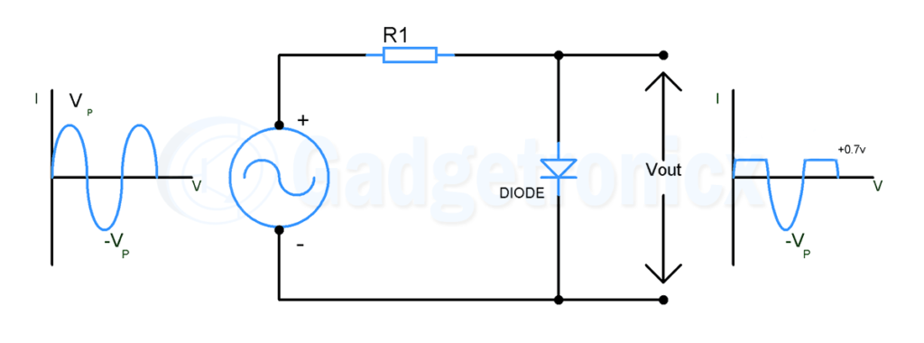
A) Positive Clipping Circuit:

The figure above shows a positive clipping circuit. Here, the AC signal source is connected to a resistor and a diode in series. During the positive half cycle, the diode conducts current and hence only 0.7v (typical forward voltage of a diode) will appear in the output. This is because in order for a diode to conduct current, the input voltage should exceed the forward voltage. In other words, the signal will be clipped to +0.7v. Meanwhile, during the negative half cycle, the diode will be reverse biased and zero current will flow through it, leaving the voltage across the terminals unchanged. This is how it works as a positive clipping circuit.
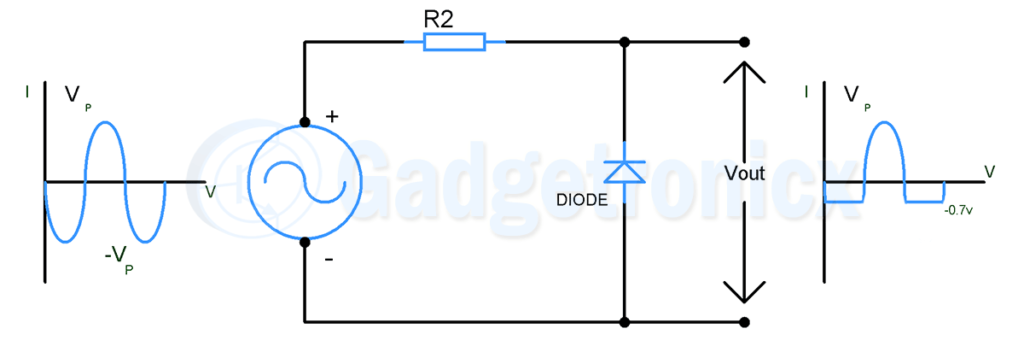
b) Negative Clipping Circuit:

The figure above shows a negative clipping circuit. The direction of the diode here is opposite to what we saw in the positive clipper. This way, when the positive cycle of the AC signal passes through, it will be reverse biased, blocking the current flow and keeping the voltage unchanged. Therefore, the positive cycle will show up in the output. While during the negative half cycle, the diode will be forward biased and current will flow through it. Therefore, the negative half cycle of the signal is clipped to -0.7v, equivalent to its forward voltage.
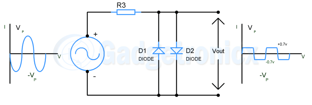
C) Positive and negative clipping circuit:

The circuit diagram shown in the figure above is a positive and negative clipping circuit. This is nothing but a combination of positive and negative clipping circuits. Here, you can see two diodes placed in parallel with each other but in different directions. When an AC signal is provided, diode D1 clips the positive half cycle of the circuit while diode D2 clips the negative half cycle of the signal. So, in the output, you will see a signal that is clipped in both the half cycles at 0.7v and -0.7v voltage levels.
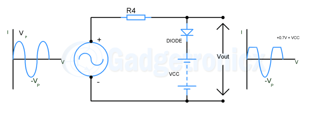
D) Bias Clipping Circuit:

Sometimes we need to clip a circuit at a voltage level higher than the forward voltage of the diode. In these cases, we can use a voltage source to provide the necessary bias and force the clipping voltage to the desired level. In the above circuit, you can observe that the peak voltage of the AC signal is V
p/-Vp, and when using a voltage source VCC in a positive clipping circuit, the voltage required by the AC signal to force current through the diode will increase from 0.7v to 0.7v +
VCC. For example, using a 4v supply as VCC will clip the positive half cycle at 4.7v voltage level. This is helpful when we need to limit the signal to a desired voltage level. We can also clip the positive and negative half cycles at the desired level and can clip them at different levels.
- Working principle/advantages/disadvantages/size of optical fiber
- Why use PWM? What are its advantages?
- Touch circuit design and analysis
- Experiment and production of NE555 time base integrated circuit
- Homemade 100-base addition and subtraction counting circuit
- Square wave frequency multiplier (SN15844N, SN7400N)
- Phase-locked Frequency Multiplier(9316)
- 150-300MHz frequency multiplier composed of MC1596
- Symmetrical output three-way frequency circuit (74LS109, 74LS113)
- Unity-gain buffer circuit composed of MAX4100/MAX4101
- How to judge the positive and negative poles of diodes
- Power diode analysis
- Car voice-based mobile phone call reminder
- Wireless microphone circuit
- Bridge connection of two power op amps
- Motorcycle ignition circuit diagram
- Input status indication circuit diagram
- Thyristor cut-off delay circuit 6
- Internal structure of MC1411 series Darlington current driver d
- Multiple sets of colorful light chain circuits that flash in cycles (Part 3)


 京公网安备 11010802033920号