At present, electric locomotives use mechanical foot switches to send trigger pulses (110V/0V) to the monitor at a fixed time (within 1 minute) to inform the monitor that the locomotive driver is in a normal duty state to ensure the normal operation of the locomotive. Since the foot switch is a mechanical contact switch and is not sealed, after the switch is stored in the warehouse or used for a period of time, the contact will oxidize, age and accumulate dust, causing poor contact failure. As a result, the locomotive driver cannot judge the effectiveness of each foot switch action. The monitor cannot receive the trigger pulse regularly and give an alarm signal; at the same time, the locomotive driver's job responsibilities cannot be implemented. Using a non-contact electronic foot switch can solve the above technical problems well.
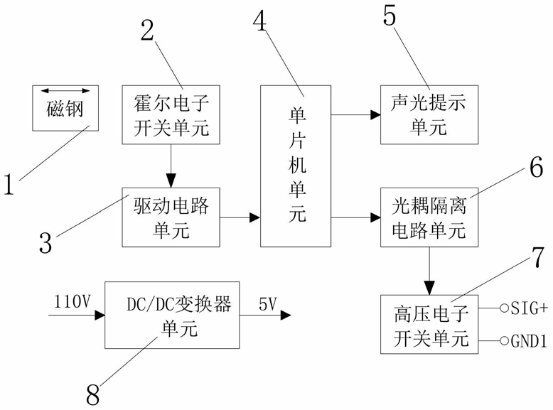
The foot switch includes a magnet, a Hall electronic switch unit, a drive circuit unit, a single-chip unit, an audio and video prompt circuit unit, an optocoupler isolation circuit unit, a high-voltage electronic switch unit, and a DC/DC converter unit. The magnet is arranged at the front side of the Hall electronic switch, the Hall electronic switch unit is connected to the driving circuit unit, the driving circuit unit is connected to the single-chip unit, the single-chip unit is connected to the sound and light prompt circuit unit and the optical coupling isolation circuit unit, the optical coupling isolation circuit unit is connected to the high-voltage electronic switch unit, and the output end of the DC/DC converter unit is connected to the power input end connected to the single-chip unit, the Hall electronic switch unit, the sound and light prompt circuit unit and the optical coupling isolation circuit unit. The magnet is a cylindrical thin NdFeB magnet, the Hall electronic switch unit adopts a Hall effect sensor of model DRV5013 (or a domestic automotive-grade product CHA442), the DC/DC converter unit adopts 110V to 5V, and the single-chip unit adopts a single-chip STC11F04.

Figure 1 Structure diagram

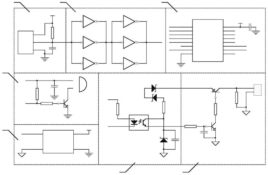
Figure 2 Application circuit diagram
Working process and principle:
The magnet 1 moves close to the Hall sensor, triggering the Hall electronic switch, causing its output to change from a high level to a low level.
The Hall electronic switch unit 2 is composed of a Hall sensor U1 (CHA442), R1 and C1, and is used to receive the electromagnetic signal of the approaching magnet and convert it into an electrical signal.
The driving circuit unit 3 is composed of U2 (74HC04), and the three NOT gates connected in parallel can provide a driving current greater than 30mA.
The single chip unit 4 is composed of U3 (STC11F04) and peripheral components, which are used to improve the driving capability and anti-interference ability of the circuit.
The sound and light prompt circuit unit 5 is composed of V3 (2N2222), BU1, R6 and R7, and is used for alarm prompt.
The optocoupler isolation circuit unit 6 is composed of U4 (TLP521), D1-2 (1N4753/36V), D3 (1N4742/12V), R2, R8, and D1-2, D3 and R8 form a voltage stabilizing circuit.
The high-voltage electronic switch unit 7 includes: V1 (MUE13001), V2 (2SB546), R3 (10K), R4 (27K/1W), R5 (20K/2W), C4 (1uF) and P1. R3 and C4 form a delay circuit to prevent the output of a high level when the power is turned on. The high-voltage electronic switch is used to simulate a trigger pulse.
The DC/DC converter unit 8 converts 110 VDC into 5 VDC (VCC) for powering the control circuit.
The CHA442 mentioned in this article is a series of digital bipolar latch Hall sensor products that meet AEC-Q100 automotive certification. The main performance and features of the CCHA44X series products are as follows:
• AEC-Q100 automotive qualified
• Digital Bipolar Latch Hall Sensor
• Multiple sensitivity options (BOP / BRP): +15 / -15G; +30 / -30G; +45 / -45G; +120 / -120G;
• Chopper with stable operating point over the entire operating temperature range
• On-board voltage regulator in the range of 2.5V to 22V
• Output short circuit protection
• Reverse battery and freewheeling protection
• Insensitive to physical stress
• Wide operating temperature range: -40 to 150°C
• Small package sizes TO-92S, SOT-23 and SOT-89
• RoHS compliant materials directive 2011/65/EU

Product Application:
1. Speed and RPM Sensing
2. Tachometer, counter pickup
3. Flow sensor
4. Brushless DC (direct current) motor commutation
5. Motor and fan control
6. Robot control

Product Description:
The CH441/CH442/CH443/CH444 Hall effect sensors are extremely temperature stable and stress resistant and are particularly suited for operation over the -40°C to 150°C temperature range. Excellent high temperature performance is achieved through dynamic offset cancellation, which reduces the residual offset voltage stress typically caused by device overmolding, temperature dependence, and thermal effects. The device includes a voltage regulator, Hall voltage generator, small signal amplifier, chopper stabilization, Schmitt trigger, and short circuit protection for the open drain output down to 25 mA. The on-board voltage regulator allows operation with supply voltages from 2.5 to 22 V. The advantage of operation down to 2.5 V is that the device can be used in 2.5 V applications or with an additional external resistor in series with the supply pin for increased protection against high voltage transient events. The CH441/CH442/CH443/CH444 series are latching Hall switches. For latching mode, reverse polarity devices are also available. A south pole of sufficient strength turns the output on under normal conditions; however, a north pole of sufficient strength turns the output on for reverse polarity devices. The CH441/CH442/CH443/CH444 also incorporate internal clamps to protect against power/output transients; output short circuit protection; and reverse battery conditions.
Functional Description
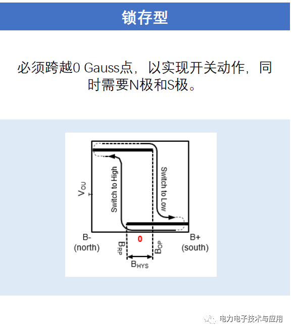
The CHA44X/CH44X has a latching magnetic switching characteristic. Therefore, it requires both a south and north pole for normal operation. The device behaves as a latch with symmetrical operation and release switching points (BOP=|BRP|). This means that magnetic fields with equal strength and opposite directions drive the output high and low. Removing the magnetic field (B→0), it holds the output in its previous state. This latching characteristic defines the device as a magnetic memory. The hysteresis BHYST keeps BOP and BRP between minimum values. This hysteresis prevents output oscillations around the switching point.
Magnetic action characteristics


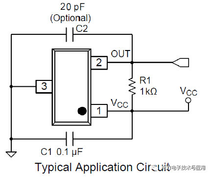
Typical Applications
It is recommended to connect an external capacitor C1 to the power supply. This reduces noise injected into the device. A normal 0.1uF is recommended.

Hall Switches & Latches

Previous article:Learn more about Soitec’s SmartSiC technology
Next article:Brief analysis of the basic working principle of the resistive rotary transformer
- Popular Resources
- Popular amplifiers
- Huawei's Strategic Department Director Gai Gang: The cumulative installed base of open source Euler operating system exceeds 10 million sets
- Analysis of the application of several common contact parts in high-voltage connectors of new energy vehicles
- Wiring harness durability test and contact voltage drop test method
- Sn-doped CuO nanostructure-based ethanol gas sensor for real-time drunk driving detection in vehicles
- Design considerations for automotive battery wiring harness
- Do you know all the various motors commonly used in automotive electronics?
- What are the functions of the Internet of Vehicles? What are the uses and benefits of the Internet of Vehicles?
- Power Inverter - A critical safety system for electric vehicles
- Analysis of the information security mechanism of AUTOSAR, the automotive embedded software framework
 Professor at Beihang University, dedicated to promoting microcontrollers and embedded systems for over 20 years.
- Innolux's intelligent steer-by-wire solution makes cars smarter and safer
- 8051 MCU - Parity Check
- How to efficiently balance the sensitivity of tactile sensing interfaces
- What should I do if the servo motor shakes? What causes the servo motor to shake quickly?
- 【Brushless Motor】Analysis of three-phase BLDC motor and sharing of two popular development boards
- Midea Industrial Technology's subsidiaries Clou Electronics and Hekang New Energy jointly appeared at the Munich Battery Energy Storage Exhibition and Solar Energy Exhibition
- Guoxin Sichen | Application of ferroelectric memory PB85RS2MC in power battery management, with a capacity of 2M
- Analysis of common faults of frequency converter
- In a head-on competition with Qualcomm, what kind of cockpit products has Intel come up with?
- Dalian Rongke's all-vanadium liquid flow battery energy storage equipment industrialization project has entered the sprint stage before production
- Allegro MicroSystems Introduces Advanced Magnetic and Inductive Position Sensing Solutions at Electronica 2024
- Car key in the left hand, liveness detection radar in the right hand, UWB is imperative for cars!
- After a decade of rapid development, domestic CIS has entered the market
- Aegis Dagger Battery + Thor EM-i Super Hybrid, Geely New Energy has thrown out two "king bombs"
- A brief discussion on functional safety - fault, error, and failure
- In the smart car 2.0 cycle, these core industry chains are facing major opportunities!
- The United States and Japan are developing new batteries. CATL faces challenges? How should China's new energy battery industry respond?
- Murata launches high-precision 6-axis inertial sensor for automobiles
- Ford patents pre-charge alarm to help save costs and respond to emergencies
- New real-time microcontroller system from Texas Instruments enables smarter processing in automotive and industrial applications
- Recruitment: Executive Vice President of Automotive Electronics (Executive Vice President of New Energy)
- ATmega4809 Curiosity Nano Review + Unboxing and Powering on
- Sell an unused Jiuxintaike oscilloscope and get a Guwei desktop multimeter for free
- MSP430F1232 external 4M crystal oscillator cannot start
- Q: How do you determine the inductance value when selecting a common-mode coil?
- What does BMS device learning and chemical ID mean?
- [NUCLEO-L452RE Review] + Simple Digital Voltmeter
- Gaoyun FPGA various manuals
- [2022 Digi-Key Innovation Design Competition] ESP32S2 Lighting
- PCB connector connection method

 A brief analysis of the flip implementation methods of Sharp SH9020C and NOTO ME511


 京公网安备 11010802033920号