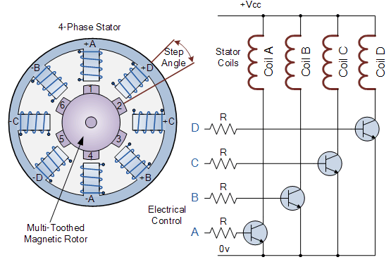
Modern multi-pole, multi-tooth stepper motors have a step accuracy of less than 0.9 degrees (400 pulses per revolution) and are mainly used in highly accurate positioning systems, such as those for magnetic heads in floppy disks/hard drives, printers/plotters or robotic applications. The most commonly used stepper motor is the 200-step-per-revolution stepper motor. It has a 50-tooth rotor, a 4-phase stator and a step angle of 1.8 degrees (360 degrees/(50×4)).
The structure and control of stepper motor

In the simple example of a variable reluctance stepper motor above, the motor consists of a central rotor surrounded by four electromagnetic field coils labelled A, B, C and D. All coils with the same letter are connected together so that applying power to, for example, a coil labelled A will cause the magnetic rotor to align with that set of coils.
By energizing each set of coils in sequence, the rotor can be rotated or "stepped" from one position to an angle determined by its step angle configuration, and by energizing the coils in sequence, the rotor will produce rotational motion.
A stepper motor driver controls the step angle and speed of the motor by energizing the field coils in a set sequence (e.g. “ADCB, ADCB, ADCB, A…”, etc.) and the rotor will rotate in one direction (forward), reversing the pulse sequence to “ABCD, ABCD, ABCD, A…”, etc. and the rotor will rotate in the opposite direction (reverse).
So in the simple example above, the stepper motor has four coils, making it a 4-phase motor, and the number of poles on the stator is eight (2 x 4), with each phase spaced 45 degrees apart. The number of teeth on the rotor is six, spaced 60 degrees apart.
The rotor then has 24 (6 teeth x 4 coils) possible positions or "steps" to complete one full revolution. Therefore, the above step angle is: 360° / 24 = 15°.
Obviously, more rotor teeth and/or stator coils will result in more control and smaller step angles. Likewise, by connecting the motor's electrical coils in different configurations, full-step, half-step and micro-step angles can be achieved. However, to achieve micro-stepping, the stepper motor must be driven by a (quasi-)sinusoidal current, which is expensive to achieve.
The speed of a stepper motor's rotation can also be controlled by varying the time delay (frequency) between the digital pulses applied to the coils. The longer the delay, the slower the speed for one full revolution. By applying a fixed number of pulses to the motor, the motor shaft will rotate a given angle.
The advantage of using a time-delayed pulse is that no additional feedback of any kind is required, since by counting the number of pulses supplied to the motor the final position of the rotor is known accurately. This response to a set number of digital input pulses allows the stepper motor to be operated in an "open loop system", making control easy and cheap.
For example, let's say our stepper motor above has a step angle of 3.6 degrees per step. To make the motor rotate, for example, 216 degrees and then stop at the desired position, a total of: 216 degrees / (3.6 degrees / step) = 80 pulses are required to be applied to the stator coils.
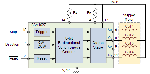
There are many stepper motor controller ICs available which can control stepping speed, rotation speed and motor direction. The SAA1027 is one such controller IC which has all the necessary counters and code conversion functions built in and can automatically drive 4 fully controlled bridge outputs to the motor in the correct sequence.
The direction of rotation can also be selected with single-step mode or continuous (stepless) rotation in the selected direction, but this places some burden on the controller. When using an 8-bit digital controller, 256 microsteps per step can also be achieved
SAA1027 stepper motor control chip

In this tutorial about Rotary Actuators, we looked at brushed and brushless DC motors, DC servomotors, and stepper motors, which are electromechanical actuators that can be used as output devices for position or velocity control.
Previous article:Detailed explanation of the three major control points of servo, stepper and frequency conversion
Next article:PLC control of robot interference area and interlock signal control
Recommended ReadingLatest update time:2024-11-16 11:24


- Popular Resources
- Popular amplifiers
-
 西门子S7-12001500 PLC SCL语言编程从入门到精通 (北岛李工)
 -
 New Energy Vehicle Detection and Diagnosis Experiment (Edited by Mao Caiyun, Zhou Xien, and Long Jiwen)
 -
 Virtualization Technology Practice Guide - High-efficiency and low-cost solutions for small and medium-sized enterprises (Wang Chunhai)
 -
 ESP32-S3 source code
- Huawei's Strategic Department Director Gai Gang: The cumulative installed base of open source Euler operating system exceeds 10 million sets
- Analysis of the application of several common contact parts in high-voltage connectors of new energy vehicles
- Wiring harness durability test and contact voltage drop test method
- Sn-doped CuO nanostructure-based ethanol gas sensor for real-time drunk driving detection in vehicles
- Design considerations for automotive battery wiring harness
- Do you know all the various motors commonly used in automotive electronics?
- What are the functions of the Internet of Vehicles? What are the uses and benefits of the Internet of Vehicles?
- Power Inverter - A critical safety system for electric vehicles
- Analysis of the information security mechanism of AUTOSAR, the automotive embedded software framework
 Professor at Beihang University, dedicated to promoting microcontrollers and embedded systems for over 20 years.
- Innolux's intelligent steer-by-wire solution makes cars smarter and safer
- 8051 MCU - Parity Check
- How to efficiently balance the sensitivity of tactile sensing interfaces
- What should I do if the servo motor shakes? What causes the servo motor to shake quickly?
- 【Brushless Motor】Analysis of three-phase BLDC motor and sharing of two popular development boards
- Midea Industrial Technology's subsidiaries Clou Electronics and Hekang New Energy jointly appeared at the Munich Battery Energy Storage Exhibition and Solar Energy Exhibition
- Guoxin Sichen | Application of ferroelectric memory PB85RS2MC in power battery management, with a capacity of 2M
- Analysis of common faults of frequency converter
- In a head-on competition with Qualcomm, what kind of cockpit products has Intel come up with?
- Dalian Rongke's all-vanadium liquid flow battery energy storage equipment industrialization project has entered the sprint stage before production
- Allegro MicroSystems Introduces Advanced Magnetic and Inductive Position Sensing Solutions at Electronica 2024
- Car key in the left hand, liveness detection radar in the right hand, UWB is imperative for cars!
- After a decade of rapid development, domestic CIS has entered the market
- Aegis Dagger Battery + Thor EM-i Super Hybrid, Geely New Energy has thrown out two "king bombs"
- A brief discussion on functional safety - fault, error, and failure
- In the smart car 2.0 cycle, these core industry chains are facing major opportunities!
- The United States and Japan are developing new batteries. CATL faces challenges? How should China's new energy battery industry respond?
- Murata launches high-precision 6-axis inertial sensor for automobiles
- Ford patents pre-charge alarm to help save costs and respond to emergencies
- New real-time microcontroller system from Texas Instruments enables smarter processing in automotive and industrial applications
- MOS Specifications
- MSP430 high version software download low version program
- Milliohm meter-expansion board design based on [EVAL-ADICUP360]
- Xunwei-i.MX6ULL Development Board-Network Test Method (Part 2)
- esp8266 uses oled to play online videos
- Security monitoring multi-channel long-distance transmission problem
- Why does LDMOS conduct without adding gate voltage?
- EEWORLD University Hall----Live Replay: NXP's facial recognition technology solution based on i.MX RT106F
- Function overloading and reentrancy
- Alternative winners in the 5G era


 西门子S7-12001500 PLC SCL语言编程从入门到精通 (北岛李工)
 ESP32-S3 source code


 京公网安备 11010802033920号