By varying the amount of base current flowing into the transistor, the speed of the motor can be controlled, for example, if the transistor is "halfway" on, only half the supply voltage flows to the motor. If the transistor is "fully on" (saturated), all the supply voltage flows to the motor and it spins faster. Then, for this linear control type, power is constantly delivered to the motor as shown below.
Motor speed control

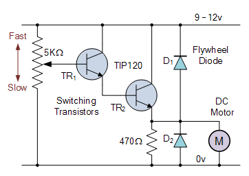
The simple switch circuit above shows the circuit for a unidirectional (one direction only) motor speed control circuit. Since the speed of a DC motor is proportional to the voltage across its terminals, we can use a transistor to regulate this terminal voltage.
The two transistors are connected as a Darlington pair to control the main armature current of the motor. A 5kΩ potentiometer is used to control the amount of base drive to the first pilot transistor TR1, which in turn controls the main switching transistor, TR2 allowing the DC voltage of the motor to vary from zero to Vcc, in this embodiment 9 to 12 volts.
An optional flywheel diode is connected across the switching transistor TR 2 and the motor terminals to prevent back EMF generated when the motor is spinning. The adjustable potentiometer can be replaced by a continuous logic "1" or logic "0" signal applied directly to the input of the circuit to turn the motor "fully on" (saturation) or "fully off" (cut-off), respectively, from the port of a microcontroller or PIC.
In addition to basic speed control, the same circuit can be used to control the speed of a motor. By repeatedly switching the motor current "ON" and "OFF" at a high enough frequency, the speed of the motor can be varied between stationary (0 rpm) and full speed (100%) by varying the mark-space ratio of its supply. This can be achieved by varying the ratio of the "on" time (tON) to the "off" time (tOFF), and can be achieved using a process called pulse width modulation.
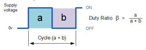
Pulse Width Speed Control We have said before that the speed of a DC motor is proportional to the value of the average (mean) voltage across its terminals, and that the higher this value is, up to the maximum permissible motor voltage, the faster the motor will spin. In other words, the higher the voltage, the faster the speed. By varying the ratio between the "on" (tON) time and the "off" (tOFF) duration, known as the "duty cycle", "mark/space ratio" or "duty cycle", it follows that the motor voltage and therefore its speed can be varied. For a simple unipolar drive, the duty cycle β is:

The average DC output voltage fed to the motor is: Vmean = β x Vsupply. Then, by varying the width of the pulse a, the motor voltage can be controlled, and thus the power applied to the motor can be controlled. This type of control is called pulse width modulation or PWM.
Another way to control the speed of a motor is to vary the frequency (and the period of time the control voltage is applied) while keeping the "on" and "off" duty cycle times constant. This type of control is called pulse frequency modulation, or PFM.
With pulse frequency modulation, the motor voltage is controlled by applying pulses of variable frequency, e.g. at a low frequency or with only a few pulses, the average voltage applied to the motor is low and therefore the motor speed is slow. At a higher frequency or with many pulses, the average motor terminal voltage increases and the motor speed also increases.
The transistor can then be used to control the power applied to the DC motor, with the operating modes being "linear" (the voltage to the motor varies), "pulse width modulation" (the width of the pulses varies), or "pulse frequency modulation" (varying the frequency of the pulses).
Reversing the Direction of a DC Motor Although controlling the speed of a DC motor with a single transistor has many advantages, it also has one major disadvantage, the direction of rotation is always the same, making it a "unidirectional" circuit. In many applications, we need to operate the motor in both the forward and reverse directions.
To control the direction of a DC motor, the polarity of the DC power applied to the motor's connections must be reversed to cause its shaft to rotate in the opposite direction.
A very simple and cheap way to control the direction of rotation of a DC motor is to use different switches arranged in the following way:
DC Motor Direction Control

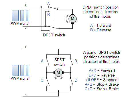
The first circuit uses a single double-pole double-throw (DPDT) switch to control the polarity of the motor connections. By switching the contacts, the power to the motor terminals can be reversed and the direction of the motor can be reversed. The second circuit is a little more complex and uses four single-pole single-throw (SPST) switches in an "H" configuration.
Mechanical switches are arranged in pairs and must be operated in specific combinations to operate or stop a DC motor. For example, as shown in the figure, switch combination A+D controls forward rotation, while switches B+C control reverse rotation. Combination switches A+B or C+D short-circuit the motor terminals, causing it to brake quickly. However, using switches in this manner has its dangers, because operating switches A+C or B+D together shorts out the power supply.
While the above two circuits work well for most small DC motor applications, do we really want to operate different combinations of mechanical switches just to reverse the direction of the motor? We could change the manual switches of the electromechanical relay bank and have a single forward/reverse button or switch, or even use a solid-state CMOS 4066B four-sided bidirectional switch.
However, another great way to achieve bidirectional control of the motor (and thus its speed) is to connect the motor to a transistor H-bridge type circuit arrangement as shown below.
Basic Bidirectional H-Bridge Circuit

The H-bridge circuit above, so named because four switches, either electromechanical relays or transistors resemble the letter "H" with the basic structure of a motor located on the center bar. The transistor or MOSFET H-bridge is probably one of the most commonly used types of bidirectional DC motor control circuits. It uses "complementary transistor pairs" of NPN and PNP in each branch, with the transistors switched together in pairs to control the motor.
Control input A runs the motor in one direction (forward rotation) and input B runs the motor in the other direction (i.e. reverse rotation). Direction control of the motor is then achieved by switching the transistors in their "diagonal pairs" either "ON" or "OFF".
For example, when transistor TR1 is "ON" and transistor TR2 is "OFF", point A is connected to the supply voltage (+Vcc), and if transistor TR3 is "OFF" and transistor TR4 is "ON", point B is connected to 0 volts (GND). The motor will then rotate in one direction with motor terminal A being positive and motor terminal B being negative.
If the switching states are reversed so that TR1 is "OFF", TR2 is "ON", TR3 is "ON", and TR4 is "OFF", the motor current will flow in the opposite direction, causing the motor to rotate in the reverse direction.
Then, by applying opposite logic levels "1" or "0" to input terminals A and B, the direction of rotation of the motor can be controlled as follows.
H-bridge truth table

It is important that no other input combination is allowed, as this could result in a short circuit in the supply, i.e. both transistors TR1 and TR2 being switched "ON" at the same time (fuse = explosion!).
Just like the unidirectional DC motor control we saw above, it is also possible to control the speed of the motor using pulse width modulation or PWM. Then, by combining H-bridge switching with PWM control, the direction and speed of the motor can be precisely controlled.
Commercial off-the-shelf decoder ICs such as the SN754410 quad half H-bridge IC or the L298N with 2 H-bridges provide all the necessary control and safety logic built in that is specifically designed for H-bridge bidirectional motor control circuits.
DC stepper motors are electromechanical actuators that convert pulsed digital input signals into discrete (incremental) mechanical movements, and are widely used in industrial control applications. Stepper motors are a type of synchronous brushless motor that does not have an armature with a commutator and carbon brushes, but rather has a rotor consisting of many rotors, some types of rotors have hundreds of permanent magnet teeth, and a stator with a single winding.
Stepper Motor
As the name implies, a stepper motor does not rotate continuously like a regular DC motor, but instead moves in discrete "steps" or "increments", with the angle of each rotation or step being determined by the number of stator poles and rotor teeth of the stepper motor.
Because of their discrete stepping operation, a stepper motor can easily rotate a limited portion of a rotation at a time, such as 1.8, 3.6, 7.5 degrees, etc. So, for example, let's say a stepper motor completes a full revolution (360°) in 100 steps.
Then, the step angle of the motor is 360 degrees / 100 steps = 3.6 degrees per step. This value is usually called the stepper motor "step angle".
There are three basic types of stepper motors, variable reluctance, permanent magnet and hybrid (a combination of the two). A stepper motor is particularly suitable for applications that require precise positioning and repeatability along with fast response of starting, stopping, reversing and speed control with another key feature of a stepper motor being the ability to hold a load steady once the desired position is achieved.
Typically, a stepper motor has an internal rotor with a large number of permanent magnet "teeth" and multiple electromagnet "teeth" mounted on a stator. The stator electromagnets are polarized and depolarized in sequence, causing the rotor to rotate one "step" at a time.
Previous article:Detailed explanation of the three major control points of servo, stepper and frequency conversion
Next article:PLC control of robot interference area and interlock signal control
Recommended ReadingLatest update time:2024-11-16 11:24


- Popular Resources
- Popular amplifiers
-
 西门子S7-12001500 PLC SCL语言编程从入门到精通 (北岛李工)
 -
 New Energy Vehicle Detection and Diagnosis Experiment (Edited by Mao Caiyun, Zhou Xien, and Long Jiwen)
 -
 Virtualization Technology Practice Guide - High-efficiency and low-cost solutions for small and medium-sized enterprises (Wang Chunhai)
 -
 ESP32-S3 source code
- Huawei's Strategic Department Director Gai Gang: The cumulative installed base of open source Euler operating system exceeds 10 million sets
- Analysis of the application of several common contact parts in high-voltage connectors of new energy vehicles
- Wiring harness durability test and contact voltage drop test method
- Sn-doped CuO nanostructure-based ethanol gas sensor for real-time drunk driving detection in vehicles
- Design considerations for automotive battery wiring harness
- Do you know all the various motors commonly used in automotive electronics?
- What are the functions of the Internet of Vehicles? What are the uses and benefits of the Internet of Vehicles?
- Power Inverter - A critical safety system for electric vehicles
- Analysis of the information security mechanism of AUTOSAR, the automotive embedded software framework
 Professor at Beihang University, dedicated to promoting microcontrollers and embedded systems for over 20 years.
- Innolux's intelligent steer-by-wire solution makes cars smarter and safer
- 8051 MCU - Parity Check
- How to efficiently balance the sensitivity of tactile sensing interfaces
- What should I do if the servo motor shakes? What causes the servo motor to shake quickly?
- 【Brushless Motor】Analysis of three-phase BLDC motor and sharing of two popular development boards
- Midea Industrial Technology's subsidiaries Clou Electronics and Hekang New Energy jointly appeared at the Munich Battery Energy Storage Exhibition and Solar Energy Exhibition
- Guoxin Sichen | Application of ferroelectric memory PB85RS2MC in power battery management, with a capacity of 2M
- Analysis of common faults of frequency converter
- In a head-on competition with Qualcomm, what kind of cockpit products has Intel come up with?
- Dalian Rongke's all-vanadium liquid flow battery energy storage equipment industrialization project has entered the sprint stage before production
- Allegro MicroSystems Introduces Advanced Magnetic and Inductive Position Sensing Solutions at Electronica 2024
- Car key in the left hand, liveness detection radar in the right hand, UWB is imperative for cars!
- After a decade of rapid development, domestic CIS has entered the market
- Aegis Dagger Battery + Thor EM-i Super Hybrid, Geely New Energy has thrown out two "king bombs"
- A brief discussion on functional safety - fault, error, and failure
- In the smart car 2.0 cycle, these core industry chains are facing major opportunities!
- The United States and Japan are developing new batteries. CATL faces challenges? How should China's new energy battery industry respond?
- Murata launches high-precision 6-axis inertial sensor for automobiles
- Ford patents pre-charge alarm to help save costs and respond to emergencies
- New real-time microcontroller system from Texas Instruments enables smarter processing in automotive and industrial applications
- MOS Specifications
- MSP430 high version software download low version program
- Milliohm meter-expansion board design based on [EVAL-ADICUP360]
- Xunwei-i.MX6ULL Development Board-Network Test Method (Part 2)
- esp8266 uses oled to play online videos
- Security monitoring multi-channel long-distance transmission problem
- Why does LDMOS conduct without adding gate voltage?
- EEWORLD University Hall----Live Replay: NXP's facial recognition technology solution based on i.MX RT106F
- Function overloading and reentrancy
- Alternative winners in the 5G era


 西门子S7-12001500 PLC SCL语言编程从入门到精通 (北岛李工)
 ESP32-S3 source code


 京公网安备 11010802033920号