Servo control
1. Working principle of AC servo motor
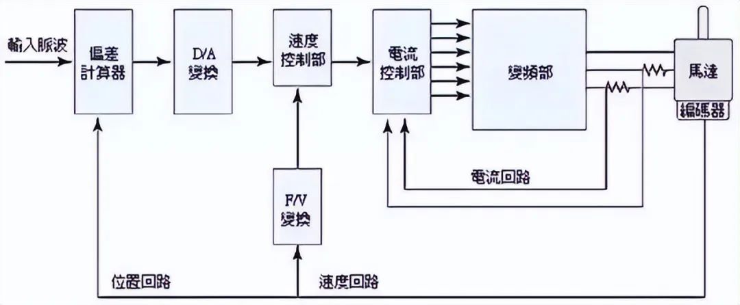
The rotor inside the servo motor is a permanent magnet. The U/V/W three-phase electricity controlled by the driver forms an electromagnetic field. The rotor rotates under the action of this magnetic field. At the same time, the encoder of the motor feeds back the signal to the driver. The driver compares the feedback value with the target value and adjusts the angle of rotation of the rotor. The accuracy of the servo motor is determined by the accuracy of the encoder (number of lines).
2. Composition and classification of servo system
composition:
The servo system is a general term for control systems that use position and angle as control variables. Systems that use speed, angular velocity, acceleration, force, etc. related to position and angle as control variables are also included in the servo system.
Classification:
1. According to the control structure, it can be divided into open loop and closed loop.
2. According to the driving components, it can be divided into:
a. Stepper motor servo system.
b. DC motor servo system.
c. AC motor servo system.
3. Characteristics of servo motor (AC)
1. High positioning accuracy, ordinary servo motor can reach 0.036 degrees
2. Fast response time.
3. The control is convenient and flexible, and the control system is easy to implement.
4. There are many models, and different types can be selected according to different application environments.
5. Provide full closed-loop control, monitor the operating status in a timely manner and make appropriate adjustments and changes.
4. Servo system structure

5. Servo control selection steps
1. Determine the mechanical specifications, load, rigidity and other parameters.
2. Confirm the motion parameters, moving speed, stroke, acceleration and deceleration time, cycle, accuracy, etc.
3. Select the motor inertia, load inertia, motor shaft conversion inertia, and rotor inertia.
4. Select the motor rotation speed.
5. Select the rated torque of the motor, load torque, acceleration/deceleration torque, instantaneous maximum torque, and effective torque.
6. Select the motor mechanical position resolution.
7. Select the motor model based on the above.
6. Application of servo control

Stepper control
1. Working principle of stepper motor
A stepper motor is an actuator that converts electrical pulses into angular displacement. When the stepper driver receives a pulse signal, it drives the stepper motor to rotate a fixed angle (called the "step angle") in the set direction. Its rotation is performed step by step at a fixed angle. The angular displacement can be controlled by controlling the number of pulses to achieve accurate positioning; at the same time, the speed and acceleration of the motor can be controlled by controlling the pulse frequency to achieve speed regulation. Stepper motors can be used as a special motor for control. They are widely used in various open-loop controls due to their lack of accumulated error (accuracy of 100%).
2. Classification of stepper motors
The more commonly used stepper motors now include reactive stepper motors (VR), permanent magnet stepper motors (PM), hybrid stepper motors (HB) and single-phase stepper motors.
Permanent magnet stepper motors are generally two-phase, with small torque and volume, and the step angle is generally 7.5 degrees or 15 degrees;
Reactive stepper motors are generally three-phase, can achieve high torque output, and the step angle is generally 1.5 degrees, but the noise and vibration are very large. The rotor magnetic circuit of the reactive stepper motor is made of soft magnetic material, and there are multi-phase excitation windings on the stator, which uses the change of magnetic permeance to generate torque.
Hybrid stepper motors are those that combine the advantages of permanent magnet and reactive stepper motors. They are divided into two-phase and five-phase stepper motors: the two-phase stepper angle is generally 1.8 degrees and the five-phase stepper angle is generally 0.72 degrees. This type of stepper motor is the most widely used.
3. Stepper motor system

1. Terminology of static indicators of stepper motors
a. Phase number: the number of pairs of exciting coils that produce N and S magnetic fields of different polarities. Usually represented by m.
b. Beat number: The number of pulses or conductive states required to complete a periodic change of the magnetic field is represented by n, or it refers to the number of pulses required for the motor to rotate through one pitch angle.
c. Step angle: Corresponding to a pulse signal, the angular displacement of the motor rotor is represented by θ.
d. Detent torque: The locking torque of the motor rotor itself when the motor is not powered (caused by the harmonics of the magnetic field tooth shape and mechanical errors).
e. Static torque: The locking torque of the motor shaft when the motor is under rated static electrical action and the motor is not rotating.
2. Stepper motor dynamic indicators and terminology
a. Step angle accuracy: the error between the actual value and the theoretical value of each step angle of the stepper motor.
b. Step loss: When the number of steps of the motor is not equal to the theoretical number of steps, it is called step loss.
c. Misalignment angle: The angle at which the rotor tooth axis is offset from the stator tooth axis.
d. Maximum no-load starting frequency: The maximum frequency at which the motor can be started directly without load under a certain drive form, voltage and rated current.
e. Maximum no-load operating frequency: The maximum speed frequency of the motor without load under a certain drive form, voltage and rated current.
f. Operating torque-frequency characteristics: The curve of the relationship between the output torque and frequency of the motor measured under certain test conditions during operation is called the operating torque-frequency characteristics.
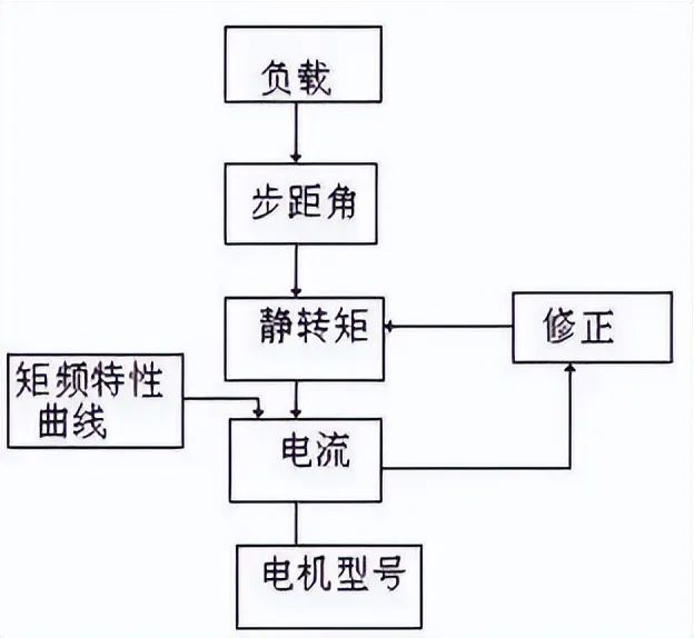
4. Stepper motor selection
1. Selection of step angle: The step angle of the motor depends on the load accuracy requirements.
2. Selection of static torque: The basis for selecting static torque is the load of the motor. Generally, the static torque should be within 2-3 times of the friction load.
3. Current selection: Due to different current parameters, the operating characteristics vary greatly. The motor current can be determined based on the torque-frequency characteristic curve.

5. Some characteristics of stepper motors
1. The accuracy of a general stepper motor is 3-5% of the step angle and is not cumulative.
2. The maximum allowable temperature of the stepper motor surface is generally above 130 degrees Celsius.
3. The torque of a stepper motor decreases as the speed increases.
4. The stepper motor can run normally at low speed, but if it exceeds a certain speed, it cannot start and is accompanied by a howling sound.
5. Stepper motors are used in low-speed applications - the speed does not exceed 1000 revolutions per minute.
6. Performance comparison of the two motors
1. Different control accuracy. The step angle of the five-phase hybrid stepper motor is generally 0.72° and 0.36°. The control accuracy of the AC servo motor is guaranteed by the rotary encoder at the rear end of the motor shaft. For a motor with a standard 2500-line encoder, the pulse equivalent is 360°/10000=0.036°. The servo motor has higher accuracy than the stepper motor.
2. Low-frequency characteristics: Asynchronous motors are prone to low-frequency vibration at low speeds. AC servo motors run very smoothly and will not vibrate even at low speeds.

3. Overload capacity Asynchronous stepper motors generally do not have overload capacity. AC servo motors have stronger overload capacity.
4. The control of stepper motors with different running performance is open-loop control. If the starting frequency is too high or the load is too large, it is easy to lose steps or stall. If the speed is too high when stopped, it is easy to overshoot. The AC servo drive system is closed-loop control. The driver can directly sample the feedback signal of the motor encoder. The internal position loop and speed loop are constructed. Generally, the stepper motor will not lose steps or overshoot, and the control performance is more reliable.
5. Speed response performance Different stepper motors need 200 to 400 milliseconds to accelerate from standstill to operating speed (generally several hundred revolutions per minute). AC servo systems have better acceleration performance. For example, Panasonic MSMA 400W AC servo motors only take a few milliseconds to accelerate from standstill to its rated speed of 3000RPM, which can be used in control situations that require fast start and stop.
6. The output torque of a stepper motor with different torque-frequency characteristics decreases as the speed increases, and it drops sharply at higher speeds. The AC servo motor has a constant torque output.
In summary, AC servo systems are superior to stepper motors in many aspects. However, stepper motors are often used as actuator motors in some occasions with low requirements. Therefore, in the design process of the control system, it is necessary to comprehensively consider factors such as control requirements and cost, and select appropriate control motors.

Frequency Control
1. Introduction to general motors
The three-phase squirrel cage AC motor is the most common type of induction motor. Its structure and characteristics are as follows:

Schematic diagram of the structure of an induction motor

Schematic diagram of the motor structure


Motor characteristics
2. Principle and composition of frequency converter
The frequency converter is a control device that can easily and freely change the speed of the AC motor. The method of changing the speed of the AC motor is as follows. The frequency converter achieves speed regulation by changing the power supply frequency of the AC motor:
Previous article:Sharing the method of starting multiple motors simultaneously with one inverter
Next article:The most complete analysis of DC motor working principle and control circuit (brushless + brush + servo + stepper)
- Huawei's Strategic Department Director Gai Gang: The cumulative installed base of open source Euler operating system exceeds 10 million sets
- Analysis of the application of several common contact parts in high-voltage connectors of new energy vehicles
- Wiring harness durability test and contact voltage drop test method
- Sn-doped CuO nanostructure-based ethanol gas sensor for real-time drunk driving detection in vehicles
- Design considerations for automotive battery wiring harness
- Do you know all the various motors commonly used in automotive electronics?
- What are the functions of the Internet of Vehicles? What are the uses and benefits of the Internet of Vehicles?
- Power Inverter - A critical safety system for electric vehicles
- Analysis of the information security mechanism of AUTOSAR, the automotive embedded software framework
 Professor at Beihang University, dedicated to promoting microcontrollers and embedded systems for over 20 years.
- Innolux's intelligent steer-by-wire solution makes cars smarter and safer
- 8051 MCU - Parity Check
- How to efficiently balance the sensitivity of tactile sensing interfaces
- What should I do if the servo motor shakes? What causes the servo motor to shake quickly?
- 【Brushless Motor】Analysis of three-phase BLDC motor and sharing of two popular development boards
- Midea Industrial Technology's subsidiaries Clou Electronics and Hekang New Energy jointly appeared at the Munich Battery Energy Storage Exhibition and Solar Energy Exhibition
- Guoxin Sichen | Application of ferroelectric memory PB85RS2MC in power battery management, with a capacity of 2M
- Analysis of common faults of frequency converter
- In a head-on competition with Qualcomm, what kind of cockpit products has Intel come up with?
- Dalian Rongke's all-vanadium liquid flow battery energy storage equipment industrialization project has entered the sprint stage before production
- Allegro MicroSystems Introduces Advanced Magnetic and Inductive Position Sensing Solutions at Electronica 2024
- Car key in the left hand, liveness detection radar in the right hand, UWB is imperative for cars!
- After a decade of rapid development, domestic CIS has entered the market
- Aegis Dagger Battery + Thor EM-i Super Hybrid, Geely New Energy has thrown out two "king bombs"
- A brief discussion on functional safety - fault, error, and failure
- In the smart car 2.0 cycle, these core industry chains are facing major opportunities!
- The United States and Japan are developing new batteries. CATL faces challenges? How should China's new energy battery industry respond?
- Murata launches high-precision 6-axis inertial sensor for automobiles
- Ford patents pre-charge alarm to help save costs and respond to emergencies
- New real-time microcontroller system from Texas Instruments enables smarter processing in automotive and industrial applications
- Highly recommend a good introductory book on digital signal processing
- How to Design Anti-interference for Single Chip Microcomputer
- AD, how to draw dot-dash lines on the mechanical layer?
- Analysis of concurrent execution and scheduling of RT-Thread system tasks
- Capacitive touch MSP430FR2676 MCU motherboard
- ESP32 simple Bluetooth support shared by foreign netizens
- TI document: How to program a DSP
- Live broadcast with prizes | Registration is open for TI chip technology to help motor development!
- 80-bit extended precision floating point in OCaml
- Tutorial: How to use Vivado HLS to accelerate algorithm development on FPGA


 Arduino Development Guide: STM32
 500 Cases of Electrical Maintenance of FANUC CNC Machine Tools


 京公网安备 11010802033920号