Overview
The MAX3580 is a direct conversion tuner for Digital Video Terrestrial Broadcasting (DVB-T). This article discusses the case where adding a duplex filter to the input of the MAX3580 can improve the second-order input intercept point (IIP2). The integrated input switch allows the MAX3580 to select one of the duplex filters to pass signals in the desired frequency band while rejecting signals in the interfering frequency band. This feature makes duplex filters particularly suitable for DVB-T applications, since the frequency range specified by DVB-T includes two separate frequency bands. Since the two frequency bands are independent of each other, when it is necessary to suppress signals in one of the frequency bands, only one set of duplex filters needs to be selected. By suppressing signals in the interference frequency band, the second-order distortion index can be improved, because the factors causing second-order distortion come from the interference frequency band.
Operating Principle
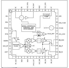
The MAX3580 fully integrated direct-conversion tuner covers the input frequency range of 170MHz to 230MHz (VHF-III) and 470MHz to 878MHz (UHF). The MAX3580 integrates an RF input switch and multi-band tracking filter, providing a low-power tuner solution without considering the cost and power consumption issues in the secondary frequency conversion solution. This zero-IF architecture eliminates all surface acoustic filters and directly outputs baseband I/Q signals.
 Figure 1. MAX3580 functional block diagram |
Duplex Filter
Since two independent frequency bands (VHF and UHF) are used in DVB-T applications, a duplex filter can be used to work with the MAX3580 input switch to improve the second-order input intercept point (IIP2). performance and suppress strong out-of-band signals. The integrated input switch is shown in Figure 1, and Figure 2 and Table 1 are the recommended duplex filters. Both inputs of the duplex filter are connected to the antenna. The output of the VHF filter is connected to the RFIN2 pin of the MAX3580, and the output of the UHF filter is connected to the RFIN pin of the MAX3580.
When the receiver is tuned to the VHF band, the input switch is set to receive signals through a low-pass filter that passes signals in the VHF band while suppressing signals in the UHF band. Likewise, when the receiver is tuned to the UHF band, the input switch is set to receive the signal through a high-pass filter that passes signals in the UHF band while rejecting signals in the VHF band. Figure 3 shows the frequency response curves of these two filters measured on the MAX3580 evaluation kit (rev 1).
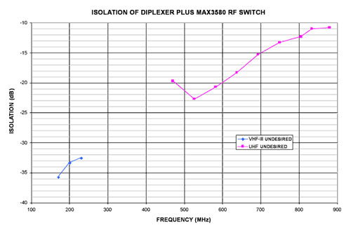
The duplex filter is used with the MAX3580, and the isolation from interference bands measured on the same evaluation board is shown in Figure 4. When tuned to the VHF band, the signal in the UHF band is attenuated by 15dB (typical value); when tuned to the UHF band, the signal in the VHF band is attenuated by at least 32dB.
This proprietary approach improves IIP2 with minimal impact on overall noise figure. The improvement of IIP2 in the VHF band is attributed to the attenuation of the UHF band, which produces AB distortion in the VHF band. Likewise, the improvement in UHF band IIP2 is attributed to the attenuation of VHF band signals, which produces A+B and AB distortion in the UHF band.
As can be seen from Table 2: For the selected input frequency and LO, the IIP2 of the duplex filtering scheme is improved by more than 30dB, and the noise figure is reduced by less than 0.8dB. It can be seen from Figure 4 that IIP2 has been improved in other aspects, and IIP2 has been improved by isolating out-of-band input signals. When both input frequencies are outside the band, the sum of the attenuation for both is the improvement in IIP2. Therefore, when the input frequency is 707.5MHz, 878MHz, and the LO frequency is 170MHz, IIP2 can still be improved by 25dB.
 Figure 2. MAX3580 duplex filter schematic |
  ? ? Figure 3. Rejection and insertion loss of duplex filter |
 Figure 4. Isolation between frequency bands when using a duplex filter with the MAX3580 |
Table 2. What is the impact of duplex filter on IIP2 improvement and NF performance  ? ? |
Conclusion
By using a discrete duplex filter in conjunction with the MAX3580 DVB-T integrated tuning IC, the second-order input intercept point (IIP2) can be improved by more than 25dB and the suppression of out-of-band signals is enhanced, at the expense of reducing the noise figure of the receiving system. , but only reduced by 0.8dB.
Previous article:Digital filter design based on DSP C54x
Next article:Temperature Compensation Method for Monolithic Relaxation Oscillator
Recommended ReadingLatest update time:2024-11-17 03:02
- Popular Resources
- Popular amplifiers
-
 Computer Vision Applications in Autonomous Vehicles: Methods, Challenges, and Future Directions
 -
 Semantic Segmentation for Autonomous Driving: Model Evaluation, Dataset Generation, Viewpoint Comparison, and Real-time Performance
 -
 Investigation of occupancy perception in autonomous driving: An information fusion perspective
 -
 CVPR 2023 Paper Summary: Physics-based Vision and Shape-from-X
- High signal-to-noise ratio MEMS microphone drives artificial intelligence interaction
- Advantages of using a differential-to-single-ended RF amplifier in a transmit signal chain design
- ON Semiconductor CEO Appears at Munich Electronica Show and Launches Treo Platform
- ON Semiconductor Launches Industry-Leading Analog and Mixed-Signal Platform
- Analog Devices ADAQ7767-1 μModule DAQ Solution for Rapid Development of Precision Data Acquisition Systems Now Available at Mouser
- Domestic high-precision, high-speed ADC chips are on the rise
- Microcontrollers that combine Hi-Fi, intelligence and USB multi-channel features – ushering in a new era of digital audio
- Using capacitive PGA, Naxin Micro launches high-precision multi-channel 24/16-bit Δ-Σ ADC
- Fully Differential Amplifier Provides High Voltage, Low Noise Signals for Precision Data Acquisition Signal Chain
- Innolux's intelligent steer-by-wire solution makes cars smarter and safer
- 8051 MCU - Parity Check
- How to efficiently balance the sensitivity of tactile sensing interfaces
- What should I do if the servo motor shakes? What causes the servo motor to shake quickly?
- 【Brushless Motor】Analysis of three-phase BLDC motor and sharing of two popular development boards
- Midea Industrial Technology's subsidiaries Clou Electronics and Hekang New Energy jointly appeared at the Munich Battery Energy Storage Exhibition and Solar Energy Exhibition
- Guoxin Sichen | Application of ferroelectric memory PB85RS2MC in power battery management, with a capacity of 2M
- Analysis of common faults of frequency converter
- In a head-on competition with Qualcomm, what kind of cockpit products has Intel come up with?
- Dalian Rongke's all-vanadium liquid flow battery energy storage equipment industrialization project has entered the sprint stage before production
- Allegro MicroSystems Introduces Advanced Magnetic and Inductive Position Sensing Solutions at Electronica 2024
- Car key in the left hand, liveness detection radar in the right hand, UWB is imperative for cars!
- After a decade of rapid development, domestic CIS has entered the market
- Aegis Dagger Battery + Thor EM-i Super Hybrid, Geely New Energy has thrown out two "king bombs"
- A brief discussion on functional safety - fault, error, and failure
- In the smart car 2.0 cycle, these core industry chains are facing major opportunities!
- Rambus Launches Industry's First HBM 4 Controller IP: What Are the Technical Details Behind It?
- The United States and Japan are developing new batteries. CATL faces challenges? How should China's new energy battery industry respond?
- Murata launches high-precision 6-axis inertial sensor for automobiles
- Ford patents pre-charge alarm to help save costs and respond to emergencies
- Review summary: Anxinke NB-IoT development board EC-01F-Kit
- Open Source Tutorial | Design of Smart Ecological Fish Tank
- Please tell me what type of inductor this is
- Feedback coefficient expression calculation
- I am a newcomer to the switching power supply industry and need to learn how to calculate the counter-transformer. Do you have any good experience or t...
- Elimination of low frequency signals
- Where can I find the German patent number?
- EK140 Burning Guide
- Two small questions about the lithium battery charging chip bq2407x
- Operating System Timeline and Family Tree

 Computer Vision Applications in Autonomous Vehicles: Methods, Challenges, and Future Directions
 CVPR 2023 Paper Summary: Physics-based Vision and Shape-from-X


 京公网安备 11010802033920号