This paper discusses the high-frequency field distribution of slotted cylindrical waveguides and presents a self-consistent nonlinear theory of injection-wave interaction. Under the condition of large cyclotron motion of electrons and considering velocity dispersion, the injection-wave interaction of the third harmonic cyclotron traveling-wave amplifier with slotted waveguide of uniform cross-section is numerically calculated by the fourth-order Runge-Kutta method. Some important interaction laws are obtained, which lays a foundation for further research on cyclotron traveling-wave amplifiers.
Keywords: cyclotron traveling-wave amplifier; slotted waveguide; self-consistent nonlinearity; high-order harmonics; velocity dispersion
Self-Consistent Nonlinear Theory and Simulation of a Slotted Third-Harmonic Gyro-TWT Amplifier
ZHANG Hong-bin,LI Hong-fu,ZHOU Xiao-lan,WANG Hua-jun,YU Sheng,DU Pin-zhong
(Inst.of High Energy Electronics,UEST of China,Chengdu 610054,China)
Abstract:The distribution of RF field of the slotted cylindrincal wave guide is discussed and the self-consistent nonlinear theory of the beam-wave interaction is presented in this paper.The behavior of the slotted gyrotron traveling-wave amplifier (gyro-TWT) with a uniform section is simulated by a Runge-Kutta algorithm code for a warm beam encircling around the axis of the wave guide. Some important regulations are obtained. This work presents the bases to further studies of the gyro-TWT.
Key words:Gyro- TWT; slotted wave guide; self-consistent nonlinear; high harmonic wave; velocity spread
I. Introduction
Gyrotron traveling wave amplifiers are millimeter wave amplifiers. They are known for their high power, high efficiency, and wide bandwidth. They have extremely important application prospects in the fields of radar and communication. Since the late 1970s, they have made great progress in both theory and experiment [1-5].
For fundamental harmonic gyrotron traveling wave tubes, a very high DC magnetic field is required in the millimeter wave band, so a large superconducting system or electromagnet system is required to provide the DC magnetic field. The use of high-order harmonic interaction can greatly reduce the tube's requirements for the DC magnetic field [2,3], making it possible to use permanent magnets, thereby greatly reducing the volume of the tube. Due to the difference in high-frequency field distribution between slotted and smooth-wall waveguides, slotted waveguides are more conducive to injection wave interaction, have lower operating voltage requirements, and have higher operating efficiency than smooth-wall waveguides. At the same time, compared with smooth-wall waveguides, they have better mode competition suppression capabilities [6]. This paper takes the 95GHz slotted third harmonic as an example to perform numerical simulations on gyrotron traveling wave amplifiers and obtains some important interaction laws.
2. High-frequency field mode and characteristics
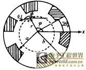
Figure 1 shows the slotted waveguide structure and the cross-sectional view of the electron beam trajectory (the dotted circle represents the cross-sectional view of the electron beam). Let N be the number of slots in the slotted waveguide, θ0 be the gap half angle, a and b be the inner and outer radii of the waveguide respectively, r, φ, z be the cylindrical coordinates of the electron, v⊥ be the transverse velocity of the electron, φ be the momentum space angle, that is, the angle between v⊥ and the x-axis. For the sake of convenience, the waveguide is divided into two regions for discussion, namely: Region I (0<r<a) and Region II (a<r<b). Since the effective interaction field between the electron beam and the wave in the cyclotron traveling wave tube is the TE wave field, we only need to be concerned with the distribution of the high-frequency field of the transverse electric wave [7~9]. Here, only the expression of the high-frequency electric field component is given, and the expression of the high-frequency magnetic field component can be further obtained through the relationship between the electromagnetic field components.
|
Figure 1 Schematic diagram of the cross section of the hollow outer slot waveguide and the electron beam. The dotted circle is the schematic diagram of the cross section of the electron beam In zone I (0<r<a)
In zone II (a<r<b)
Ez=0 (4)
in
In the above formulas, E0 is the high-frequency field amplitude, Γ is the angular harmonic number, ΑΓ is the amplitude coefficient of the angular Γ subharmonic term, kc is the cutoff wave number, q is the slot number (q=1,2,…,N), and m represents the angular mode of the high-frequency field (m=0,1,2,…,N-1). The value of ΑΓ and the dispersion relation of the circuit can be determined by the boundary conditions of the electromagnetic field at r=a.
The dispersion relation is
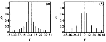
Equation (9) shows that non-zero spatial harmonic terms exist only when the spatial harmonic order Γ=m+lN. The angular mode determines the phase difference of the high-frequency field between adjacent gaps. For each specific mode, this phase difference is m2π/N. Each angular mode is composed of countless angular harmonic terms, and its harmonic amplitude coefficient is determined by equation (9). Among all angular modes, there are two relatively important modes, namely the π mode and the 2π mode. The relative strength distribution of their angular harmonics is shown in Figure 2. As can be seen from Figure 2, the energy of the 2π mode is mainly concentrated in the zero-order harmonic term, while the energy of the π mode is mainly concentrated in the ±N/2-order harmonic terms. Therefore, the π mode is more suitable for high-order cyclotron harmonic interactions than the 2π mode. If the electron beam cyclotron harmonic order (represented by S) has been set, then the selection of the slot number N should ensure that the order Γ of the strongest non-zero angular harmonic term is equal to the cyclotron harmonic order S. For example, for the π mode, the slot number N should be equal to 2S. |
|
Fig. 2 Schematic diagram of the relative distribution of angular harmonic amplitude to angular harmonic number (Γ). (a) π mode (m=N/2, N=6, θ0=15°), (b) 2π mode (m=0, N=6, θ0=15°) When the angular mode m and the groove depth (i.e., the value of a/b) are determined, the cutoff wave number kc can be obtained by numerical solution method using equation (10) [6, 8, 9].
3. Self-consistent nonlinear theory
In the above formulas, Cmn is the normalization coefficient of the electric field, and f(z) is a complex function representing the slowly varying distribution of the high-frequency field along the Z axis. The value of Cmn is obtained by the following formula:
The following is a set of ordinary differential equations for self-consistent nonlinear beam-wave interaction.
Starting
In the above equations, m0 and γ are the rest mass and relativistic factor of the electron, φ is the momentum space angle, u=γv, v is the speed of the electron, as shown in Figure 1.
In the above formula, P is the number of electron beam batches taken in one high-frequency field cycle, M is the number of circles into which the electron beam is divided considering the electron beam thickness factor, N is the number of macro electrons taken in each circle, and S is the harmonic order.〈…〉 represents the averaging of the velocity space with the initial velocity distribution function of g0(v⊥,vz). Assuming that the electron beam is a monoenergetic electron beam, the velocity dispersion mainly comes from the dispersion of the horizontal and vertical velocity ratio (V⊥/Vz). Here, the velocity dispersion is handled according to the normal distribution law, that is, the initial velocity distribution function is
Where K is the normalization constant, △vz is the average longitudinal velocity dispersion, and δ is the Dirac function.
f(z)|z=0=f(0) (19)
Where f(0) is the input high-frequency electric field amplitude.
IV. Results and Discussion
Table 1 Numerical simulation parameters and results |
| Inner radius | 1.024mm |
| Outer Radius | 1.465mm |
| Circuit length | 87.9mm |
| Note voltage | 60kV |
| Injection current | 6A |
| α | 1.3 |
| DC magnetic field | 11.674kG |
| High frequency field mode | π |
| Harmonic Order | 3 |
| Operating frequency | 95.08GHz |
| Simulation Results | |
| Saturation efficiency | 22.8% |
| Saturated output power | 82kW |
| Saturation Gain | 36.15dB |
|
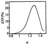
Figure 3 Relationship between efficiency and electron beam velocity ratio α (s=3,πmode,I=6A,V=60kV,ω/ωc=1.032,
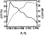
Figure 4 shows the relationship between saturation efficiency, saturation gain and B0/Bg value, and the dotted line is the saturation gain curve. In the figure, γz is the relativistic factor of the longitudinal velocity component. The figure shows that, on the one hand, reducing the B0/Bg value is helpful to improve the saturation interaction efficiency, but the B0/Bg value cannot be too low, otherwise the detuning will be aggravated, the injection wave interaction will be difficult to achieve synchronization, and the saturation efficiency will decrease rapidly; on the other hand, increasing the B0/Bg value is conducive to improving the saturation gain. In general, the selection of the magnetic field detuning rate should be an optimal compromise between efficiency and gain.
Figure 4 Relationship between saturation efficiency and gain and B0/Bg value (s=3,π mode,I=6A,V=60kV,ω/ωc=γz,
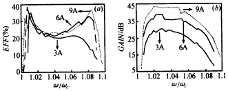
Figure 5 shows the relationship between (a) saturation efficiency and (b) saturation gain as a function of frequency when the current is 3A, 6A, and 9A. It can be seen that the saturation efficiency, saturation gain, and saturation bandwidth all increase with the increase of current. In the case of 6A and the figure, the saturation bandwidth is 7%. When the current increases from 3A to 9A, the saturation bandwidth increases from 4.6% to 8.3%. |
|
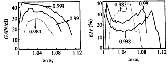
Figure 5: (a) Saturation efficiency (b) Saturation gain versus frequency at different currents (s=3,π mode,V=60kV,α=1.3,B0/Bg=0.99) Figure 6 shows the relationship between saturation gain and saturation efficiency at different magnetic field detuning rates and frequency. It can be seen from the figure that the magnetic field detuning rate has a great influence on the saturation gain, saturation efficiency and saturation bandwidth. The increase of B0/Bg value is conducive to the improvement of saturation gain and saturation bandwidth, but the saturation efficiency is reduced. Under the conditions shown in the figure, when the B0/Bg value increases from 0.983 to 0.998, the saturation bandwidth increases from 4.8% to 9.3%. |
|
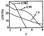
Figure 6 Relationship between (a) saturation gain and (b) saturation efficiency and frequency at different magnetic field detuning ratios (s=3,π mode,I=6A,V=60kV,α=1.3) Figure 7 shows the relationship between the saturation efficiency and the harmonic order at different magnetic field detuning rates. The figure shows that the saturation efficiency decreases with the increase of the harmonic order. The lower the B0/Bg value, the greater the impact of the harmonic order on the saturation efficiency. |
|
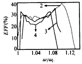
Figure 7 Saturation efficiency versus harmonic order (π mode, I=6A, V=60kV, α=1.3, ω/ωc=γz, rL/a=0.7) Figure 8 shows the relationship between saturation efficiency and frequency under different harmonic orders. The figure shows that the harmonic order has a great influence on the saturation bandwidth. Under the conditions shown in the figure, when the harmonic order increases from 2 to 4, the saturation bandwidth decreases from 10.3% to 5.7%. |
|
Figure 8 Variation of saturation efficiency with frequency at different harmonic orders (π mode, I=6A, V=60kV, α=1.3, B0/Bg=0.99, ω/ωc=γz, rL/a=0.7)
V. Conclusion
|
Previous article:How to choose a wireless microphone
Next article:Analysis and simulation of short-range application of TR-R2 multi-station radar system
- Popular Resources
- Popular amplifiers
- High signal-to-noise ratio MEMS microphone drives artificial intelligence interaction
- Advantages of using a differential-to-single-ended RF amplifier in a transmit signal chain design
- ON Semiconductor CEO Appears at Munich Electronica Show and Launches Treo Platform
- ON Semiconductor Launches Industry-Leading Analog and Mixed-Signal Platform
- Analog Devices ADAQ7767-1 μModule DAQ Solution for Rapid Development of Precision Data Acquisition Systems Now Available at Mouser
- Domestic high-precision, high-speed ADC chips are on the rise
- Microcontrollers that combine Hi-Fi, intelligence and USB multi-channel features – ushering in a new era of digital audio
- Using capacitive PGA, Naxin Micro launches high-precision multi-channel 24/16-bit Δ-Σ ADC
- Fully Differential Amplifier Provides High Voltage, Low Noise Signals for Precision Data Acquisition Signal Chain
- Innolux's intelligent steer-by-wire solution makes cars smarter and safer
- 8051 MCU - Parity Check
- How to efficiently balance the sensitivity of tactile sensing interfaces
- What should I do if the servo motor shakes? What causes the servo motor to shake quickly?
- 【Brushless Motor】Analysis of three-phase BLDC motor and sharing of two popular development boards
- Midea Industrial Technology's subsidiaries Clou Electronics and Hekang New Energy jointly appeared at the Munich Battery Energy Storage Exhibition and Solar Energy Exhibition
- Guoxin Sichen | Application of ferroelectric memory PB85RS2MC in power battery management, with a capacity of 2M
- Analysis of common faults of frequency converter
- In a head-on competition with Qualcomm, what kind of cockpit products has Intel come up with?
- Dalian Rongke's all-vanadium liquid flow battery energy storage equipment industrialization project has entered the sprint stage before production
- New breakthrough! Ultra-fast memory accelerates Intel Xeon 6-core processors
- New breakthrough! Ultra-fast memory accelerates Intel Xeon 6-core processors
- Consolidating vRAN sites onto a single server helps operators reduce total cost of ownership
- Consolidating vRAN sites onto a single server helps operators reduce total cost of ownership
- Allegro MicroSystems Introduces Advanced Magnetic and Inductive Position Sensing Solutions at Electronica 2024
- Car key in the left hand, liveness detection radar in the right hand, UWB is imperative for cars!
- After a decade of rapid development, domestic CIS has entered the market
- Aegis Dagger Battery + Thor EM-i Super Hybrid, Geely New Energy has thrown out two "king bombs"
- A brief discussion on functional safety - fault, error, and failure
- In the smart car 2.0 cycle, these core industry chains are facing major opportunities!
- Morris Chang: China's semiconductor manufacturing lags behind Taiwan by five years
- Wireless charging mouse pads from Rapoo and Jingzao are waiting for you to take them apart - EEWorld invites you to play disassembly (Part 3)
- Isolation and filtering of electromagnetic waves
- Designing Accurate and Versatile Li-ion Battery Testing Solutions
- Find library component modifications
- Please recommend a 485 automatic transceiver chip, 3.3V version.
- Which environment setup tutorial should I watch? -- ESP series development environment setup video navigation directory
- CC2640R2F-Q1 uses low-power Bluetooth technology to transform car access control systems
- Problems with opening KEIL in WIN10
- MSP430 MCU Development Record (25)

 (1)
(1)
 (2)
(2)
 (9)
(9)
 (10)
(10)
 (14)
(14)
 (15)
(15)
 (17)
(17)
 (18)
(18)
 AWT-18236-3RI


 京公网安备 11010802033920号