Among various RF power amplifier linearization technologies, feedforward technology has high linearity and bandwidth, but its circuit structure is complex, expensive, and low-efficiency. It is mainly used in high-power amplifiers and in repeaters. , pre-distortion technology has certain advantages. It has low cost, low power consumption and simple circuit structure. In a mechanically distorted RF power amplifier, the performance of the amplifier mainly depends on the characteristics of the predistorter. A good predistorter can greatly improve the linearity of the power amplifier and better suppress spectrum regeneration. This article studies a predistorter that can generate IM3 and IM5 respectively, which can improve the 3rd-order and 5th-order intermodulation components well.
1 Circuit structure of predistorter
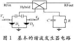
The basic harmonic generator circuit is shown in Figure 1.

This harmonic generator consists of two Schottky diodes with the same characteristics (Skyworks' SMS3922 is used in this article), capacitors, resistors and a 180° 3dB bridge coupler. The two diodes have different bias voltages, making them work in different nonlinear regions to generate distorted signals. The capacitor and resistor absorb signals within a certain band, and an equal two-tone signal Vi is added to the input end of the harmonic generator:
Vi=Acosω1t+Acosω2t (1)
Among them: A is the amplitude of the two-tone signal; ω1, ω2 are the frequencies of the two-tone signal and ω1≠ω2. And assume that the nonlinear transfer function of the harmonic generator is y=f(x), and the output is V0. That is: V0=f(Vi). Expanding it into a power series is:

By controlling the diode bias voltage, the coefficient bi (i=1, 2, 3...) in equation (2) can be appropriately adjusted, so that equation (2) can independently generate IM3 and IM5 signals. In the predistortion linear In the circuit, two harmonic generators are used, one is used to generate IM3 signals, and the other is used to generate IM5 signals. In this way, the 3rd-order intermodulation and 5th-order intermodulation components generated by the RF power amplifier can be controlled separately.
Perform a two-tone test simulation on the circuit in Figure 1 in ADS. By adjusting the bias voltage of each diode, the desired IM3 and IM5 can be generated at the output. The simulation results are shown in Figure 2(a) and (b) respectively. It can be seen from the simulation results that the output terminal also contains a fundamental frequency component. In order to cancel the fundamental frequency component, the circuit in Figure 1 must be improved and a cancellation circuit added. Add a power divider to the input end, connect one channel to the basic harmonic generator, and adjust the other channel through an attenuator and phase shifter, and then combine it with the output of the basic harmonic generator through a combiner, as shown in Figure 3 Show.


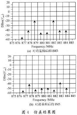
Appropriately adjust the attenuator and phase shifter so that the fundamental frequency signal of the previous branch and the fundamental frequency signal at the output end of the harmonic generator are equal in amplitude and 180° out of phase, so that the fundamental frequency signal can be canceled . The simulation results are shown in Figure 4(a) and (b).

2 test results
In order to verify the effectiveness of the predistorter studied in this article, the predistorter was applied to a 5W CDMA radio frequency power amplifier, and a two-tone test simulation was performed in ADS. The simulation circuit block diagram is shown in Figure 5.

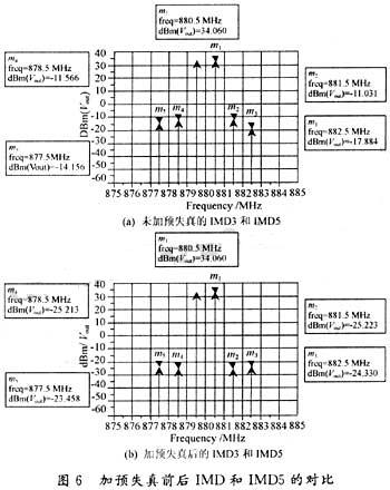
In this simulation test, the main power amplifier uses Freescale's MRF9045 radio frequency device. The vector regulator consists of an attenuator and a phase shifter, which is used to adjust the amplitude and phase of the distorted signal so that it is consistent with the third-order and fifth-order signals generated by the main power amplifier. The first-order intermodulation components are equal in amplitude and 180° out of phase to maximize the cancellation of third- and fifth-order intermodulation components. Two-tone harmonic balance simulation (2-Tone HB) is performed in ADS to test the linearity of the power amplifier. Without predistortion, when the output power of the amplifier is 5W, the distortion is large, and the two-tone intermodulation IMD3 and IMD5 are shown in Figure 6(a) respectively. When the pre-distortion technology in this article is adopted, IMD3 and IMD5 are significantly improved, as shown in Figure 6(b).

It can be seen from the simulation results that after using the pre-distortion technology in this article, IMD3 and IMD5 have improved by 14dBc and 9dBc respectively.
3 Conclusion
The effectiveness of the predistorter in this paper was confirmed in the simulation test. Using it in a 5W CDMA RF power amplifier, the two-tone test shows that IMD3 and IMD5 are significantly improved, improving by 14dBc and 9dBc respectively.
The linearization technology of using harmonic generator to achieve predistortion introduced in this article relies on adjusting the bias voltage of two diodes to generate IM3 and IM5 respectively. Therefore, it can easily be used as an adaptive control end and use an adaptive algorithm. More accurate adjustment leads to better improvements in IM3 and IM5.
Previous article:ADC and RF devices that meet the dynamic performance requirements of high-performance digital receivers
Next article:Analog preprocessing of low-frequency weak signals based on MAX260
- Popular Resources
- Popular amplifiers
- High signal-to-noise ratio MEMS microphone drives artificial intelligence interaction
- Advantages of using a differential-to-single-ended RF amplifier in a transmit signal chain design
- ON Semiconductor CEO Appears at Munich Electronica Show and Launches Treo Platform
- ON Semiconductor Launches Industry-Leading Analog and Mixed-Signal Platform
- Analog Devices ADAQ7767-1 μModule DAQ Solution for Rapid Development of Precision Data Acquisition Systems Now Available at Mouser
- Domestic high-precision, high-speed ADC chips are on the rise
- Microcontrollers that combine Hi-Fi, intelligence and USB multi-channel features – ushering in a new era of digital audio
- Using capacitive PGA, Naxin Micro launches high-precision multi-channel 24/16-bit Δ-Σ ADC
- Fully Differential Amplifier Provides High Voltage, Low Noise Signals for Precision Data Acquisition Signal Chain
- Innolux's intelligent steer-by-wire solution makes cars smarter and safer
- 8051 MCU - Parity Check
- How to efficiently balance the sensitivity of tactile sensing interfaces
- What should I do if the servo motor shakes? What causes the servo motor to shake quickly?
- 【Brushless Motor】Analysis of three-phase BLDC motor and sharing of two popular development boards
- Midea Industrial Technology's subsidiaries Clou Electronics and Hekang New Energy jointly appeared at the Munich Battery Energy Storage Exhibition and Solar Energy Exhibition
- Guoxin Sichen | Application of ferroelectric memory PB85RS2MC in power battery management, with a capacity of 2M
- Analysis of common faults of frequency converter
- In a head-on competition with Qualcomm, what kind of cockpit products has Intel come up with?
- Dalian Rongke's all-vanadium liquid flow battery energy storage equipment industrialization project has entered the sprint stage before production
- Allegro MicroSystems Introduces Advanced Magnetic and Inductive Position Sensing Solutions at Electronica 2024
- Car key in the left hand, liveness detection radar in the right hand, UWB is imperative for cars!
- After a decade of rapid development, domestic CIS has entered the market
- Aegis Dagger Battery + Thor EM-i Super Hybrid, Geely New Energy has thrown out two "king bombs"
- A brief discussion on functional safety - fault, error, and failure
- In the smart car 2.0 cycle, these core industry chains are facing major opportunities!
- Rambus Launches Industry's First HBM 4 Controller IP: What Are the Technical Details Behind It?
- The United States and Japan are developing new batteries. CATL faces challenges? How should China's new energy battery industry respond?
- Murata launches high-precision 6-axis inertial sensor for automobiles
- Ford patents pre-charge alarm to help save costs and respond to emergencies
- EEWORLD University ---- Basics of Brushless DC Motors - Drive Control
- [Artry AT32WB415 Series Bluetooth BLE 5.0 MCU Review] 3.0 Bluetooth Communication Porting
- Terasic DE10-Standard Reference Materials (Free Download, Updated from Time to Time!)
- How to prevent the motor from reversing and damaging the chip in the DC motor drive circuit
- Companies are fully aware of employees' tendency to leave, and monitoring system developers quietly remove related services
- Follow the power expert to make a "high-efficiency bidirectional DC-DC converter"
- Duty cycle setting problem
- Share how to use GPIO to simulate I2C communication on C2000
- Detailed explanation of Zigbee networking principle
- Ask a question about operating ESP8266 with STM32

 Wireless Communication Electronics:Introduction to RF Circuits and Design...


 京公网安备 11010802033920号