1 Introduction
In modern electrical measurement and control, low-voltage devices are often needed to measure and control high voltage,
High current and other analog quantities. If there is no electrical isolation between analog quantities and digital quantities, then high voltage,
Strong current can easily flow into low-voltage devices and burn them out. Linear optocoupler HCNR200 can better
Realize the isolation between analog and digital quantities, the peak isolation voltage reaches 8000V; the output follows the input
change, the linearity reaches 0.01%.
2 Introduction to HCNR200/201
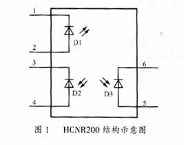
The principle of HCNR200 linear optocoupler is shown in Figure 1. It consists of light-emitting diode D1, feedback light
It is composed of electric diode D2 and output photodiode D3. When D1 passes the driving current If , it emits infrared
Light (servo luminous flux). The light is illuminated on D2 and D3 respectively, and the feedback photodiode absorbs the D2 light pass.
part of the amount, thus generating a control current I 1 (I 1 =0.005I f ). This current is used to adjust If to compensate
Compensate for the nonlinearity of D1. The output current I produced by the output photodiode D3 and the servo light emitted by D1
The amount is linearly proportional. Let the servo current gain K 1 =I 1 /I f and the forward gain K 2 =I 2 /I f , then the transmission
Gain K 3 =K 2 /K 1 =I 2 /I 1 , the typical value of K 3 is 1.
3 Current detection circuit
3.1 Current detection circuit design in photoconductivity mode The
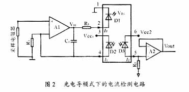
detection current circuit of HCNR200 working in photoconductivity mode is shown in Figure 2. The signal is positive
Polar input, positive polarity output. In the isolation circuit, R 1 adjusts the input bias of the primary operational amplifier
The size of the current, C 1 plays a feedback role, and at the same time filters out glitch signals in the circuit to avoid HCNR200
Aluminum gallium arsenide light-emitting diodes (LEDs) have been hit unexpectedly. However, as the frequency increases,
The impedance will become smaller, the primary current of HCNR200 will increase, and the gain will increase accordingly. Therefore, the introduction of C 1 will
The gain of the channel at high frequencies has a certain impact. Although reducing the value of C 1 can expand the bandwidth, however,
It will affect the gain of the primary operational amplifier, and at the same time, there will be a large glitch in the output of the primary operational amplifier.
The signal is not easily filtered out. R 3 can control the luminous intensity of the LED and play a role in controlling the channel gain.
certain effect.
3.2 Design of current detection circuit in photovoltage mode
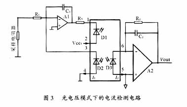
The detection current circuit of HCNR200 working in photovoltage mode is shown in Figure 3. The signal is
Positive polarity input, positive polarity output. The functions of R 1 , R 2 , R 3 and C 1 are the same as those in photoconductive mode.
The function is basically the same. Amplifier A1 regulates current If . When the input voltage V in increases, I 1 increases,
At the same time, the voltage at the "+" input terminal of amplifier A1 increases, causing the current If to increase. Since D1 and D2
Due to the connection between them, I 1 will pull the "+" input terminal voltage back to 0V, forming negative feedback. if put
The input current of amplifier A1 is very small, so the current flowing through R 1 is V in /R 1 =I 1 . Obviously,
There is a linear proportional relationship between I 1 and V in . I 1 changes stably and linearly, and I f also changes stably and linearly.
Because D3 is illuminated by D1, I 2 also changes steadily and linearly. Amplifier A2 and resistor R 2 turn I 2
Formation voltage V Out =I 2 ×R 2 .
4 Selection of operational amplifier
HCNR200/201 is a current drive device, and its LED operating current is 1mA ~ 20mA.
Therefore, the driving current of operational amplifier A1 must also reach 20mA to achieve this output current.
The output stage of operational amplifiers with high performance is generally bipolar. Therefore, it is more convenient to choose a bipolar operational amplifier.
suitable. At the same time, depending on the input voltage range, the operational amplifier is also required to have corresponding common mode input and
output capability. This design circuit uses the HA17324 integrated operational amplifier powered by a single power supply.
The output current can reach 40mA.
5 Resistor Selection
The selection of resistors in photoconductive mode is discussed below.
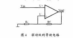
The equivalent circuit of the driver stage composed of A1 is shown in Figure 4. In the figure, R f is the equivalent feedback resistor. Should
The equivalent circuit is a typical non-inverting amplifier, so U + =U – , and U + =V in , so V in =U – .
It is obvious from Figure 2 that
![]()
In the formula, VD1 is the forward voltage drop of D1.
As can be seen from Figure 4,

Therefore, substitute equation (3) into equation (4)
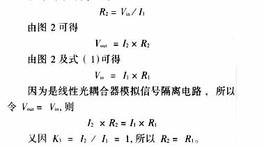
Due to the discrete nature of device parameters, I 1 is approximately equal to 0.005I f , K 3 =I 2 /I 1 ≈1, so,
R 1 , R 2 , and R 3 still need to be adjusted near the estimated values in order to obtain the best linearity.

After adjustment, the best linearity is 220Ω.
6 Conclusion
The analog signal isolation circuit composed of linear optocoupler has good linearity and simple circuit.
Effectively solves the problem of electrical isolation between analog signals and microcontroller application systems. If the driver level,
The buffer stage uses a combined operational amplifier to improve linearity.
HCNR200 can be widely used in analog signals that require good stability, linearity and bandwidth.
Number of isolation occasions. Using two HCNR200 chips, it can work in bipolar input/bipolar output mode;
At the same time, it can also work in AC and DC circuits, converter isolation, thermocouple isolation,
4mA~20mA analog current loop transmit/receive and other modes, can be widely used in digital communications,
Voltage and current detection, switching power supply , measurement and testing industrial process control, etc.
When this device is used for motor current measurement, the current feedback is accurate and reliable, and the current closed loop is realized.
played a role in control.
references
[1] Wuhan Liyuan Electronics Co., Ltd. HCNR200 Precision Linear Optocoupler Data Manual [Z], 1999.
[2] Tong Shibai . Analog Electronic Technology [M]. Beijing: Higher Education Press , 2001
|
| ||||
| ||||
Previous article:Application of MSC1211 in the development of high-precision intelligent transmitters
Next article:No EMI filter required connected to ground plane
Recommended ReadingLatest update time:2024-11-16 16:44


- Popular Resources
- Popular amplifiers
-
 Operational Amplifier Practical Reference Handbook (Edited by Liu Changsheng, Zhao Mingying, Liu Xu, etc.)
 -
 A Complete Illustrated Guide to Operational Amplifier Applications (Written by Wang Zhenhong)
 -
 Design of isolated error amplifier chip for switching power supply_Zhang Rui
 -
 DAM medium wave transmitter high frequency power amplifier module test platform_Tian Tian
- High signal-to-noise ratio MEMS microphone drives artificial intelligence interaction
- Advantages of using a differential-to-single-ended RF amplifier in a transmit signal chain design
- ON Semiconductor CEO Appears at Munich Electronica Show and Launches Treo Platform
- ON Semiconductor Launches Industry-Leading Analog and Mixed-Signal Platform
- Analog Devices ADAQ7767-1 μModule DAQ Solution for Rapid Development of Precision Data Acquisition Systems Now Available at Mouser
- Domestic high-precision, high-speed ADC chips are on the rise
- Microcontrollers that combine Hi-Fi, intelligence and USB multi-channel features – ushering in a new era of digital audio
- Using capacitive PGA, Naxin Micro launches high-precision multi-channel 24/16-bit Δ-Σ ADC
- Fully Differential Amplifier Provides High Voltage, Low Noise Signals for Precision Data Acquisition Signal Chain
- Innolux's intelligent steer-by-wire solution makes cars smarter and safer
- 8051 MCU - Parity Check
- How to efficiently balance the sensitivity of tactile sensing interfaces
- What should I do if the servo motor shakes? What causes the servo motor to shake quickly?
- 【Brushless Motor】Analysis of three-phase BLDC motor and sharing of two popular development boards
- Midea Industrial Technology's subsidiaries Clou Electronics and Hekang New Energy jointly appeared at the Munich Battery Energy Storage Exhibition and Solar Energy Exhibition
- Guoxin Sichen | Application of ferroelectric memory PB85RS2MC in power battery management, with a capacity of 2M
- Analysis of common faults of frequency converter
- In a head-on competition with Qualcomm, what kind of cockpit products has Intel come up with?
- Dalian Rongke's all-vanadium liquid flow battery energy storage equipment industrialization project has entered the sprint stage before production
- Allegro MicroSystems Introduces Advanced Magnetic and Inductive Position Sensing Solutions at Electronica 2024
- Car key in the left hand, liveness detection radar in the right hand, UWB is imperative for cars!
- After a decade of rapid development, domestic CIS has entered the market
- Aegis Dagger Battery + Thor EM-i Super Hybrid, Geely New Energy has thrown out two "king bombs"
- A brief discussion on functional safety - fault, error, and failure
- In the smart car 2.0 cycle, these core industry chains are facing major opportunities!
- The United States and Japan are developing new batteries. CATL faces challenges? How should China's new energy battery industry respond?
- Murata launches high-precision 6-axis inertial sensor for automobiles
- Ford patents pre-charge alarm to help save costs and respond to emergencies
- New real-time microcontroller system from Texas Instruments enables smarter processing in automotive and industrial applications
- New version of WEBENCH user guide
- [FS-IR02 + D1CS-D54] - 5: Linking with MCU (D1CS-D54)
- Qorvo Acquires UWB Software Provider 7Hugs Labs SAS
- Please tell me how to draw the differential line of this USB
- How is the burning of OTP chip carried out after SMD?
- MSP430FR2355 Mixed-Signal Microcontroller
- Timing Analysis 1 Static Analysis Basics
- MicroPython v1.19 is coming soon
- [EEWorld invites you to play disassembly] PISEN fast charging power bank 10500mAh 22.5W
- Application of Single Chip Microcomputer in Inverted Pendulum Control System

 Operational Amplifier Practical Reference Handbook (Edited by Liu Changsheng, Zhao Mingying, Liu Xu, etc.)


 京公网安备 11010802033920号