A multifunctional second-order universal filter can realize low-pass, high-pass and band-pass filtering simultaneously or separately, and can also be designed as an orthogonal oscillator. The pole frequency and quality factor of the circuit can be adjusted independently and accurately. The circuit uses 4 operational amplifiers">integrated operational amplifiers, 2 capacitors and 11 resistors, and the inverting terminals of all integrated operational amplifiers are virtual grounded. The universal filtering function of the circuit, the independent control of the pole frequency and quality factor, and the orthogonal sinusoidal oscillation are simulated by computer, thus proving that the filter is correct and effective.
There are two forms of universal second-order filters, one is the TT (Tow-Thomas) filter, and the other is the KHN (Kerwin-Huelsman-Newcomb) filter. Compared with the TT filter, the KHN filter can not only directly realize low-pass and band-pass filtering, but also high-pass filtering. It is widely used and is the basis of modern current mode filter design. However, the KHN filter is a universal filter with single input and three outputs, and cannot realize three-input and single-output universal filtering. Due to the limited resistance ratio, its Q value cannot be too high. Among the three integrated operational amplifiers, if the inverting terminal of one operational amplifier does not meet the virtual ground, higher requirements are placed on the operational amplifier.
In view of the status of KHN filter in modern current mode circuit, another form of KHN filter is proposed, which can not only realize single-input, three-output universal filtering, but also three-input, single-output universal filtering. The pole frequency and quality factor of the circuit can be adjusted independently and accurately, and the circuit can also be modified into an orthogonal oscillator. The circuit contains 4 general integrated operational amplifiers, 2 capacitors and 11 resistors, and the inverting input terminals of all operational amplifiers are virtual ground.
1 Circuit Principle
Figure 1 shows a versatile voltage-mode second-order circuit consisting of four op amps with one large feedback loop and two small feedback loops.

Figure 1 Four op amp multifunctional second-order circuit
Assume R1=R2=R, C1=C2=C, R5=R6, and use the MASON formula to get the sum of the gains of the three loops:

The determinant of the circuit is

The pole frequency and quality factor of the circuit are


Formula (3) shows that by adjusting R1 and R2 synchronously, the pole frequency can be adjusted independently without affecting the quality factor. Formula (4) shows that by adjusting the resistance ratio of R4 and R3, the quality factor can be adjusted independently without affecting the pole frequency, thereby achieving orthogonal adjustment of the two. It is worth noting that by adjusting R4/R3, it is easy to achieve a high Q circuit, especially when R4=R3, Q=∝, which means that the circuit becomes a sinusoidal oscillator whose frequency can be adjusted by R and C.
If Vo3=Vo, then the forward channel gains from voltage sources Vi1, Vi2, Vi3 to the output terminal Vo are respectively
 , and from the MASON formula, the corresponding transfer function is
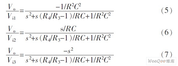
From equations (5), (6) and (7), it can be seen that if Vo3 is the output, then Vi1 is the low-pass input, Vi2 is the band-pass input, and Vi3 is the high-pass input. The circuit shown in Figure 1 is a biquadratic node that outputs signals from one port and inputs signals from three ports, respectively realizing low-pass, band-pass and high-pass second-order filtering. The corresponding gain constants are GL=-1, GB=Q, and GH=-1.
If Vi3=Vi, the forward path gains from Vi to the output terminals Vo3 and Vo1 are -1 and 1/sRC respectively.
The sum of the forward path gains from Vi to the output terminal Vo2 is
 , and the corresponding transfer function is
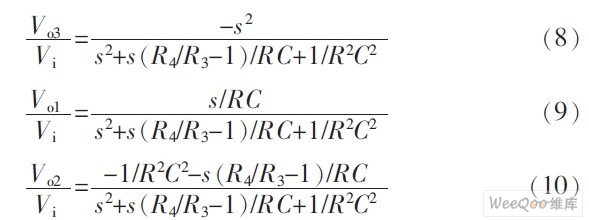
If R4/R3-1=1, then from equations (8) and (9) we can get

From equations (8) and (9), we know that if Vi3 is input, then Vo3 is high-pass output and Vo1 is band-pass output. Equations (10) and (11) show that Vo2 is not a low-pass output. When the condition R4/R3-1=1 is met, Vo1+Vo2 is a low-pass output. This is a problem worth noting. Therefore, the circuit in Figure 1 can also input signals from one port and output signals from multiple ports. It is a dual quadratic node, and simultaneously realizes high-pass, band-pass and low-pass second-order filtering. The corresponding gain constants are GB=-1, GB=Q, and GL=-1.
2 Computer simulation
In order to verify the correctness of the circuit, the circuit of Figure 1 is created on the EWB5.0 platform, in which the integrated operational amplifier is the general-purpose operational amplifier μA741. Here, only a single-input, three-output filter is simulated. Take R1= R2=R=10 kΩ, C1=C2=C=10 nF, R5=R6=10 kΩ, R4=20 kΩ, R3=10 kΩ, then the theory gives fo=1.591 5 kHz, Q=1, GB=-1, GB=1, GL=-1. The simulation results are shown in Figure 2. Using the pointer provided by EWB5.0, it can be measured that: fo=1.584 9 kHz, Q=1.011 3, GH=-1, GB=1.011 3, GL=-1.
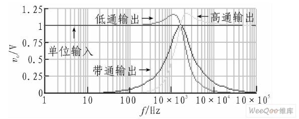
Figure 2 Simulation results of a single-input, three-output second-order filter
In order to illustrate that the quality factor of the circuit is controlled by the resistance ratio R4/R3, R1=R2=R3=R5=R6=10 kΩ, C1=C2=10 nF are still taken, and R4 is set to 12.5, 15, 17.5, and 20 kΩ respectively. The theory gives fo=1.591 5 kHz, and Q is 4, 2, 1.33, and 1 respectively. Using EWB5.0, fo=1.629 8 kHz can be measured, and Q is 4.069 0, 2.031 3, 1.350 3, and 1.010 8 respectively. The simulation results are shown in Figure 3.
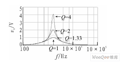
Figure 3 Simulation results of the relationship between quality factor and R4/R3
In order to illustrate that the pole frequency of the circuit is controlled by R1 and R2 and has nothing to do with R4 and R3, R3=R5=R6=10 kΩ, R4=20 kΩ, C1=C2=10nF, and R1=R2=R, respectively, when 1, 10, and 100 kΩ, the theory gives Q=1, fo is 15.915, 1.5915, and 0.15915kHz, and the frequency characteristics of the bandpass filter are shown in Figure 4. Using EWB5.0, it can be measured that fo is 16.3789, 1.6379, and 0.163 7894 kHz, respectively, and the corresponding Q is 1.1427, 1.0103, and 0.9995. Obviously, at higher frequencies, the Q enhancement phenomenon occurs, which is caused by the limited gain-bandwidth product of the operational amplifier.
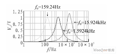
Figure 4 Simulation results of the relationship between pole frequency and R
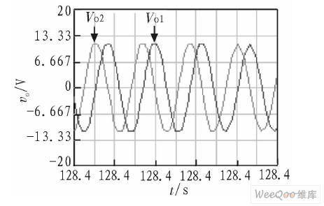
Theoretically, when R4=R3, the circuit becomes an oscillator. The simulation results show that R4 must be slightly smaller than R3 to maintain oscillation. Take R1=R2=R3=R5=R6=10 kΩ, C1=C2=10 nF, when R4=9.9 kΩ
Figure 5. Simulation results of a quadrature sinusoidal oscillator.
3 Conclusion
Using 4 general-purpose integrated operational amplifiers, 2 capacitors and 11 resistors, a second-order general-purpose filter is designed, and its parameters are set as follows: fo=1.591 5 kHz, Q=1, GB=-1, GB=1; GL=-1. This circuit can realize low-pass, band-pass and high-pass filtering with single input and multiple outputs at the same time, and can also realize low-pass, band-pass and high-pass filtering with multiple inputs and single outputs respectively. In addition to low sensitivity, the circuit also has the following characteristics: 1) The pole frequency and quality factor of the circuit can be adjusted independently, and high-Q filtering is easy to obtain; 2) The inverting input terminals of all integrated operational amplifiers are virtual grounded. Therefore, the common-mode voltage is 0, and the requirements for the operational amplifier are not high; 3) The circuit can also be adjusted into a frequency-adjustable orthogonal sine oscillator.
Previous article:HiperPFS integrated controller application circuit diagram
Next article:Design of LED driver circuit based on IR53HD420
- High signal-to-noise ratio MEMS microphone drives artificial intelligence interaction
- Advantages of using a differential-to-single-ended RF amplifier in a transmit signal chain design
- ON Semiconductor CEO Appears at Munich Electronica Show and Launches Treo Platform
- ON Semiconductor Launches Industry-Leading Analog and Mixed-Signal Platform
- Analog Devices ADAQ7767-1 μModule DAQ Solution for Rapid Development of Precision Data Acquisition Systems Now Available at Mouser
- Domestic high-precision, high-speed ADC chips are on the rise
- Microcontrollers that combine Hi-Fi, intelligence and USB multi-channel features – ushering in a new era of digital audio
- Using capacitive PGA, Naxin Micro launches high-precision multi-channel 24/16-bit Δ-Σ ADC
- Fully Differential Amplifier Provides High Voltage, Low Noise Signals for Precision Data Acquisition Signal Chain
- Innolux's intelligent steer-by-wire solution makes cars smarter and safer
- 8051 MCU - Parity Check
- How to efficiently balance the sensitivity of tactile sensing interfaces
- What should I do if the servo motor shakes? What causes the servo motor to shake quickly?
- 【Brushless Motor】Analysis of three-phase BLDC motor and sharing of two popular development boards
- Midea Industrial Technology's subsidiaries Clou Electronics and Hekang New Energy jointly appeared at the Munich Battery Energy Storage Exhibition and Solar Energy Exhibition
- Guoxin Sichen | Application of ferroelectric memory PB85RS2MC in power battery management, with a capacity of 2M
- Analysis of common faults of frequency converter
- In a head-on competition with Qualcomm, what kind of cockpit products has Intel come up with?
- Dalian Rongke's all-vanadium liquid flow battery energy storage equipment industrialization project has entered the sprint stage before production
- Allegro MicroSystems Introduces Advanced Magnetic and Inductive Position Sensing Solutions at Electronica 2024
- Car key in the left hand, liveness detection radar in the right hand, UWB is imperative for cars!
- After a decade of rapid development, domestic CIS has entered the market
- Aegis Dagger Battery + Thor EM-i Super Hybrid, Geely New Energy has thrown out two "king bombs"
- A brief discussion on functional safety - fault, error, and failure
- In the smart car 2.0 cycle, these core industry chains are facing major opportunities!
- The United States and Japan are developing new batteries. CATL faces challenges? How should China's new energy battery industry respond?
- Murata launches high-precision 6-axis inertial sensor for automobiles
- Ford patents pre-charge alarm to help save costs and respond to emergencies
- New real-time microcontroller system from Texas Instruments enables smarter processing in automotive and industrial applications
- Recruiting part-time DSP and other related professional lecturers or technical support personnel
- [CC1352P Review] TI-RTOS uartecho test
- [Erha Image Recognition Artificial Intelligence Vision Sensor] Use serial communication to conduct in-depth communication and data analysis with Erha Dog
- Electromagnetic compatibility\EMC&EMI design
- Today's broadcast starts at 10:00: TI Simplelink platform's new generation of wireless product solutions (full of highlights)
- In the development of NB-IOT LWM2M protocol device, is there a good library to facilitate the processing of AT command sending and receiving information?
- Learn Python through nursery rhymes and fairy tales
- MCU peripherals: 4Mbit, is this the maximum capacity of FRAM?
- How to ensure stable operation of RS-485 transceiver outdoors
- This week's most downloaded electronic technology materials (2020-05-09) are all classic

 VLSI Design
 AD7177 Driver


 京公网安备 11010802033920号