A water mist machine is a device that turns water into mist, which has the functions of increasing humidity, purifying air, and beautifying the environment. At present, due to the limitations of materials and technology, the amount of mist produced and the concentration of water mist in the artificial mist systems in the domestic and foreign markets are difficult to achieve the ideal effect. The mist is generally thin, and once the nozzle is fixed, the mist shape is fixed accordingly [1]. If you want to change the shape or scattering surface of the mist, you need to replace the nozzle.
In comparison, the water mist area formed by a single UFO-type water mist machine has a scattering diameter of 30 m~50 m and a thickness of 0.5 m~2 m. It has sufficient mist volume and great momentum, and can flexibly adjust different mist landscapes according to different usage environment requirements. The mist production of a single machine is equivalent to the mist production of 350~450 nozzles in the current artificial fog system on the market.
1 Basic principles
At present, the working principle of artificial fog systems in the domestic and foreign markets is similar to that of sprinkler irrigation systems. It mainly pressurizes ordinary tap water through a high-pressure unit, then transports the water to the fog-making site through a dedicated high-pressure (7 MPa~30 MPa) distribution pipeline, and finally uses a high-pressure nozzle to convert the water into fog [2]. The only difference is the atomization effect of the nozzle, working pressure and equipment performance.
In comparison, the UFO-type landscape water mist machine is a large-scale fog machine widely used indoors and outdoors, with low water and electricity consumption, energy saving and environmental protection. Its atomization working principle is to input low-pressure air (0.75 MPa~1 MPa), and under the effective control of the air valve and water valve by the control system, the water is instantly split into micron-sized water mist particles by the machine's internal core device, and then ejected from the nozzle, dispersed over a large area and suspended in the air, thus forming a huge water mist landscape with excellent indoor and outdoor viewing [3].
2 Control system design
2.1 Hardware System Design
Based on the principles of simplicity, practicality and reliability, this system uses AT 51S series microcontroller as the control core, which mainly includes four parts: input interface circuit, output control interface circuit, LED drive circuit and communication interface circuit design.
Input signal detection: This part is mainly for water level detection and day and night detection.
The water mist machine works in a pre-water storage mode and is equipped with a small water tank inside. Before spraying, make sure that the water tank is filled with water. A Hall-type float level sensor is selected for liquid level control. The sensor is sensitive and has a stable output signal, which can ensure timely output of water shortage and water fullness signals for the mainboard to collect.
The day and night detection uses the commonly used control method of photoresistor plus Schmitt trigger. By adjusting the adjustable precision resistor, the light sensing intensity is set to output the "day and night" control signal. The purpose of day and night detection is mainly to control the colorful LED lights, turning them off during the day and turning them on at night.
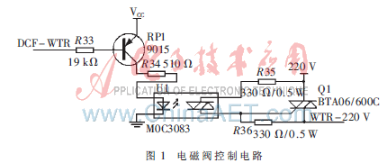
Output control: The output control of the atomizer is mainly the control of the air valve and the water valve. The water valve control is to open or close the water valve in time according to the input signal of the liquid level switch to prepare the water storage before spraying. The air valve control is to open at a predetermined time according to the system settings, input low-pressure air into the core of the atomizer for spraying, and close at a predetermined time to achieve intermittent cycle spraying. This part of the circuit uses thyristor BTA06 as the main control element, as shown in Figure 1. The DCF-WTR in the figure is an output pin of the microcontroller, indicating the control of the water valve. The control circuit of the air valve is the same.
LED drive circuit: This system is designed to install 30 small colorful LED lights, which are evenly distributed on the upper spherical surface of the flying saucer together with 28 nozzles; there are 12 colorful LED spotlights, 6 on the upper disc surface and 6 on the lower disc surface. Each lamp is composed of multiple LEDs in red (R), green (G), and blue (B) colors connected in series and parallel. The main control board is designed with 8 small colorful lamp holders and 8 colorful spotlight holders. Each lamp holder can connect up to 4 lamps in parallel. Since each lamp is composed of three colors, R, G, and B, 8 lamp holders require 3 8-bit ports, plus 8 spotlight holders, so a total of 6 8-bit ports are required. The P0 port of the microcontroller is used as the basic port for LED driving, and parallel expansion is carried out through a 3-8 decoder [4]. In this way, each lamp holder will have a certain control address.
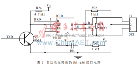
Communication interface circuit: In order to facilitate the unified coordination and control of multiple water mist machines through the host computer and achieve the dynamic spray effect of the landscape site, this system reserves the RS-485 bus interface circuit, as shown in Figure 2. The interface uses the 75176 communication chip and realizes automatic transceiver conversion through the transistor 9014 [5], which simplifies the programming. Two 1 kΩ and one 510 Ω resistors are used on the data line to ensure normal transmission and reception and enhance the system's anti-interference ability.
2.2 Control software design
2.2.1 Control algorithm design
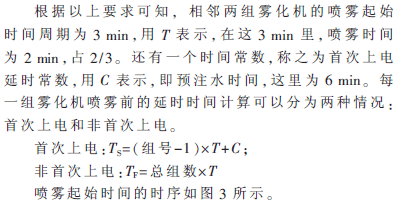
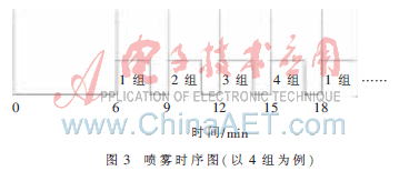
Since program-controlled water mist machines are generally distributed in multiple units in a square and controlled in linkage, a linkage control scheme needs to be set up in the absence of unified coordination and control by the host computer (i.e., offline state). The requirements are as follows: A scenic spot can be equipped with several water mist machines. According to the actual situation on site, these machines can be divided into up to 40 groups (1 to 3 machines per group). The mist machines in the same group spray at the same time at the set time, and each spray lasts 2 minutes. After the water mist machine of the adjacent group has finished spraying, it waits for 1 minute and then starts spraying, and so on. In addition, when powered on for the first time, it is necessary to fill the water tank of the water mist machine with water. It can only spray after the water is full. The pre-water filling time is set to 6 minutes.
According to the above analysis, the timer allocation of the microcontroller during programming is as follows:
T0: used to detect the photosensor and water tank liquid level height signal;
T1: used for spray timing, that is, close the air valve after 2 minutes to stop spraying, with 5 seconds as the minimum timing unit;
T2: used for delay timing before spraying, with 0.5 minutes as the minimum timing unit. The first power-on delay is TS minutes, and spraying is performed every TF minutes thereafter.
2.2.2 Software Process Design
The essence of the system control software is to accurately control the start and stop time of the spray, so the design of the timer interrupt service program is the focus of this program, and the task of the main program is relatively simple, which is to control the alternating changes of the seven-color lights. If it is daytime, turn off all lights; if it is night, turn on the lights. The main program flow is shown in Figure 4.

According to the allocation of the above timers, the service programs of T1 and T2 are the focus of compilation. Since the selected crystal oscillators are different, the clock cycles are also different. In order to achieve precise control, the relevant delay constants must be accurately calculated according to the specific crystal oscillator frequency [6]. The program of the T1 timer is relatively simple. As long as the time reaches 2 minutes, the output control closes the air valve to stop the spraying. At the same time, the volume of the background music is appropriately reduced to adapt to the surrounding environment.
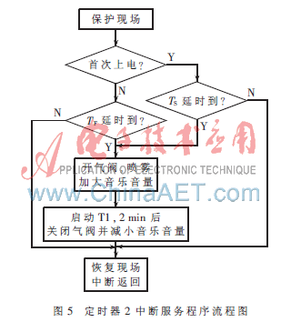
After the T2 timer enters the interrupt, in addition to the conventional on-site protection, it is also necessary to determine whether this interrupt is the first power-on interrupt, which involves whether to use TS or TF for the delay before spraying. If the timing is up, the output control opens the air valve and starts spraying, while appropriately increasing the volume of the background music to enhance the atmosphere of the landscape; if the timing is not up, the scene is restored and the interrupt service program is exited. The specific process is shown in Figure 5.
The system has become an actual product, filling the domestic gap, and has important applications in many aspects such as dust removal, irrigation, anti-static, and regulating the climate of the community, while also beautifying the environment. Practical application has proved that the system has precise control, is stable and reliable, is environmentally friendly and energy-saving, and can be mass-produced and promoted.
Previous article:Gain of 1/2 Differential Output Amplifier System
Next article:How to interface a silicon strain gauge with a large signal output to an analog-to-digital converter (ADC)
- Popular Resources
- Popular amplifiers
- High signal-to-noise ratio MEMS microphone drives artificial intelligence interaction
- Advantages of using a differential-to-single-ended RF amplifier in a transmit signal chain design
- ON Semiconductor CEO Appears at Munich Electronica Show and Launches Treo Platform
- ON Semiconductor Launches Industry-Leading Analog and Mixed-Signal Platform
- Analog Devices ADAQ7767-1 μModule DAQ Solution for Rapid Development of Precision Data Acquisition Systems Now Available at Mouser
- Domestic high-precision, high-speed ADC chips are on the rise
- Microcontrollers that combine Hi-Fi, intelligence and USB multi-channel features – ushering in a new era of digital audio
- Using capacitive PGA, Naxin Micro launches high-precision multi-channel 24/16-bit Δ-Σ ADC
- Fully Differential Amplifier Provides High Voltage, Low Noise Signals for Precision Data Acquisition Signal Chain
- Innolux's intelligent steer-by-wire solution makes cars smarter and safer
- 8051 MCU - Parity Check
- How to efficiently balance the sensitivity of tactile sensing interfaces
- What should I do if the servo motor shakes? What causes the servo motor to shake quickly?
- 【Brushless Motor】Analysis of three-phase BLDC motor and sharing of two popular development boards
- Midea Industrial Technology's subsidiaries Clou Electronics and Hekang New Energy jointly appeared at the Munich Battery Energy Storage Exhibition and Solar Energy Exhibition
- Guoxin Sichen | Application of ferroelectric memory PB85RS2MC in power battery management, with a capacity of 2M
- Analysis of common faults of frequency converter
- In a head-on competition with Qualcomm, what kind of cockpit products has Intel come up with?
- Dalian Rongke's all-vanadium liquid flow battery energy storage equipment industrialization project has entered the sprint stage before production
- Allegro MicroSystems Introduces Advanced Magnetic and Inductive Position Sensing Solutions at Electronica 2024
- Car key in the left hand, liveness detection radar in the right hand, UWB is imperative for cars!
- After a decade of rapid development, domestic CIS has entered the market
- Aegis Dagger Battery + Thor EM-i Super Hybrid, Geely New Energy has thrown out two "king bombs"
- A brief discussion on functional safety - fault, error, and failure
- In the smart car 2.0 cycle, these core industry chains are facing major opportunities!
- The United States and Japan are developing new batteries. CATL faces challenges? How should China's new energy battery industry respond?
- Murata launches high-precision 6-axis inertial sensor for automobiles
- Ford patents pre-charge alarm to help save costs and respond to emergencies
- New real-time microcontroller system from Texas Instruments enables smarter processing in automotive and industrial applications
- Reshaping the engineer experience: Tektronix invites you to attend the global launch of the new 2-series MSO at 2 pm on June 8 (today)!
- How to draw multiple boards with the same functional schematics on one PCB
- Quickly build the Hongmeng development environment for BearPi HM Nano
- Variable memory depth and segmented memory of LOTO oscilloscope
- [SAMR21 new gameplay] 21. Touchio
- STM32 learning the ninth post can not turn off the PWM pin
- I have a SOT23-6 package with a silk screen model number.
- 【CH579M-R1】+PWM breathing light and serial communication experiment
- The problem of calibrating speed
- Measuring the flow control valve signal of the auto repair actuator with an automotive oscilloscope

 A review of learning-based camera and lidar simulation methods for autonomous driving systems
 Visual ModelQ V7


 京公网安备 11010802033920号