Introduction
As discussed in the previous article in this series, designing and optimizing solutions for thermistor-based applications involves different challenges. These challenges include sensor selection and circuit configuration discussed in the previous article. Other challenges are measurement optimization – including ADC configuration and selection of external components while ensuring the ADC operates within specifications and system optimization to achieve target performance and identify error sources related to the ADC and overall system.
Thermistor System Optimization
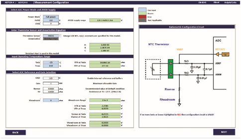
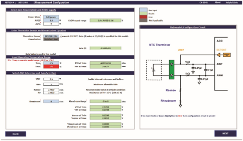
With easy-to-use tools like the Thermistor Configurator and Error Budget Calculator, customers can easily configure the thermistors in their systems, including wiring and connection diagrams. This tool designs thermistor systems with excitation voltages in a ratiometric configuration. It also allows customers to adjust settings such as sensor type, measured temperature range, linearization and external components, as shown in Figure 1. It ensures that both the ADC and thermistor sensors are used within specifications. Therefore, if a customer selects an unsupported option, the tool flags this as an error condition. For example, if the customer selects a maximum temperature value that is outside the operating range of a specific thermistor model, it will display an error, as shown in Figure 2. Following the recommended range values will also ensure that the system configuration is consistent with the operating conditions of the sensors and electronics.

Figure 1. Thermistor Configurator

Figure 2. Cross-boundary conditions
This tool enables users to understand different error sources and also allows for design optimization. Note that this tool is designed around the AD7124-4/AD7124-8, so it also determines the number of sensors that can be connected to a single ADC. To understand the importance of this tool, the different design considerations for thermistors are discussed below.
System configuration (excitation, gain, and external components)
Like RTDs, thermistors are prone to self-heating because the resistor dissipates power when current flows through it. Therefore, designers must keep the thermistor's operating current as low as possible so that its power dissipation does not significantly affect the measurement results. First, designers tend to choose higher excitation voltage values to produce higher output voltages in order to fully utilize the input range of the ADC. However, the thermistor sensor has a negative temperature coefficient, and its resistance decreases as the temperature increases, so the greater the value of current flowing through it, the higher its power consumption, resulting in self-heating.
On the plus side, thermistors do not require very high excitation source values because their higher sensitivity characteristics can produce output voltages from millivolts to volts over the rated temperature range. So, it is enough to use an excitation voltage like ADC reference voltage value and it supports ratiometric configuration. By setting the PGA gain to 1, this technique also ensures that the voltage across the thermistor's output voltage range or the ADC's analog input is always within the ADC's operating input range. This tool uses the internal 2.5V reference provided by the AD7124-4/AD7124-8. When using a gain of 1, the PGA is also turned off, thus reducing the total current consumption. The AD7124-4/AD7124-8 also integrate analog input buffers that allow any size resistor and/or capacitor values to be used externally, making them ideal for connecting directly to external resistive sensors (such as thermistors), or Electromagnetic compatibility (EMC) filtering without increasing errors. However, if the ADC is used with a gain of 1 and the analog input buffer is enabled, it is necessary to ensure that the margin required for correct operation is provided. The tool also allows designers to balance external component selection, including the allowable range of external headroom resistors, recommended sense resistor values, and their tolerance and drift performance. The Thermistor Tool also provides a list of common thermistor types and allows the designer to enter the nominal value and beta (β) or Steinhart-Hart constant for any type of NTC thermistor. The accuracy of the sensor, external components and their contribution to system error, as well as the impact of the linearization technique used for the sensor, are discussed later.
Filtering and power consumption considerations
Σ-Δ ADCs use digital filters whose frequency response provides 0dB attenuation at the sampling frequency and multiples of the sampling frequency. This means that the filter response is reflected around the sampling frequency, so an anti-aliasing filter is required in the analog domain. Σ-Δ ADCs inherently oversample the analog input signal, so the design of the anti-aliasing filter is simplified; a simple (single-pole) RC filter is sufficient. For example, the AD7124-4/AD7124-8 only require a 1kΩ resistor in series with each analog input, a 0.1µF capacitor from AINP to AINM, and a 0.01µF capacitor from each analog input pin to AVSS.
In most industrial applications or process control, strong robustness is one of the top priorities. A system may experience noise, transients, or other interference from its neighboring components or the environment. For EMC purposes, larger R and C values are often used on the analog inputs. Note, however, that when the converter is operating in unbuffered mode with a gain of 1, the input goes directly into the modulator's sampling capacitor, so larger RC values may cause gain errors because the ADC does not have enough power between the two sampling instants. time to complete the creation. Buffering the analog input prevents these errors.
Interference from AC power can also affect measurement results. Therefore, 50Hz/60Hz rejection is also a system requirement when the device is powered by AC power. Another advantage of narrowband Σ-Δ ADCs such as the AD7124-4/AD7124-8 is that it offers flexible digital filtering options that can set the notch frequency to 50Hz and/or 60Hz.
The filter type selected and the output data rate set affect settling time and its noise performance. The device also offers different power modes so the user can adjust the ADC for optimal power consumption, speed or performance. The system's current consumption or power budget allocation is highly dependent on the end application. If the system requires higher output data rates and better noise performance, the device can be configured in full power mode. If power consumption needs to be limited at reasonable speed and reasonable performance, the device can operate in medium or low power modes.
In addition to accuracy or performance, timing is also a factor. In most applications, certain time requirements need to be met in order to perform all measurements. If multiple channels are enabled (i.e., multiple sensors are used), the designer needs to consider the delay through the digital filter. In a multiplexed ADC, when multiple channels are enabled, a settling time is required each time the channel is switched. Therefore, choosing a filter type with a longer settling time (i.e. sinc4 or sinc3) will reduce the overall throughput rate. In this case, a post filter or FIR filter can be used to provide reasonable simultaneous 50 Hz/60 Hz rejection with short settling time, thereby increasing throughput rates. A subset of all filter options and output data rate selections can be tested via the thermistor configurator and error budget calculator. This will produce the desired noise performance and will feed into the system error calculation discussed in the next section. Please note that the full selection of output data rates/FS values/throughput rates is available through the Virtual Eval online tool. Virtual Eval shows timing for different scenarios and can be used to evaluate the timing performance of an ADC, whether measuring a single or multiple thermistor sensors.
Error budget calculation
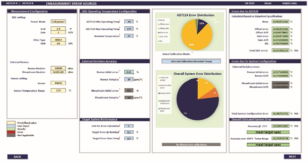
As mentioned previously, the thermistor configurator and error budget calculator allow the user to modify the system configuration for optimal performance. The error budget calculator shown in Figure 3 can help designers understand the error associated with the ADC and the error from the system configuration, regardless of whether internal or system calibration is performed. The system error pie chart indicates which part of the system contributes most to the total system error. Therefore, customers can modify the ADC or system configuration to achieve optimal performance.

Figure 3. Thermistor Error Budget Calculator
As shown in Figure 3, the error caused by the ADC is not a significant contributor to the total system error. When operating over the full temperature range, external components and their temperature coefficient or temperature drift specifications are often the primary error factors in the overall system.
For example, if we change the temperature coefficient of the sense resistor in the tool from 10ppm/°C to 25ppm/°C, you will see that the total system error increases significantly. Therefore, a sense resistor with good initial accuracy and a low temperature coefficient must be selected to minimize any possible temperature drift error.
The AD7124-4/AD7124-8 provide different calibration modes, and the use of calibration can further reduce measurement errors. It is recommended to perform internal calibration at power-up or software initialization to eliminate ADC gain and offset errors at nominal temperature. Note that this tool uses a gain setting of 1. The AD7124-4/AD7124-8 are factory calibrated for a gain of 1, and the resulting gain coefficient is the default gain coefficient of the device. Therefore, the device does not support further internal full-scale calibration at a gain of 1. Note that internal calibration at nominal temperature only removes the gain and offset errors of the AD7124-4/AD7124-8 but not those caused by external circuitry and any drift errors. Performing system calibration eliminates external errors. Performing calibration at different temperature points also improves drift performance. However, this adds cost and effort and may not be suitable for some applications.
Previous article:Thermistor-Based Temperature Detection System (Part 1): Design Challenges and Circuit Configuration
Next article:Glitch-Free Voltage Supervisor ICs—Concept or Reality?
Recommended ReadingLatest update time:2024-11-16 13:49


- High signal-to-noise ratio MEMS microphone drives artificial intelligence interaction
- Advantages of using a differential-to-single-ended RF amplifier in a transmit signal chain design
- ON Semiconductor CEO Appears at Munich Electronica Show and Launches Treo Platform
- ON Semiconductor Launches Industry-Leading Analog and Mixed-Signal Platform
- Analog Devices ADAQ7767-1 μModule DAQ Solution for Rapid Development of Precision Data Acquisition Systems Now Available at Mouser
- Domestic high-precision, high-speed ADC chips are on the rise
- Microcontrollers that combine Hi-Fi, intelligence and USB multi-channel features – ushering in a new era of digital audio
- Using capacitive PGA, Naxin Micro launches high-precision multi-channel 24/16-bit Δ-Σ ADC
- Fully Differential Amplifier Provides High Voltage, Low Noise Signals for Precision Data Acquisition Signal Chain
- Innolux's intelligent steer-by-wire solution makes cars smarter and safer
- 8051 MCU - Parity Check
- How to efficiently balance the sensitivity of tactile sensing interfaces
- What should I do if the servo motor shakes? What causes the servo motor to shake quickly?
- 【Brushless Motor】Analysis of three-phase BLDC motor and sharing of two popular development boards
- Midea Industrial Technology's subsidiaries Clou Electronics and Hekang New Energy jointly appeared at the Munich Battery Energy Storage Exhibition and Solar Energy Exhibition
- Guoxin Sichen | Application of ferroelectric memory PB85RS2MC in power battery management, with a capacity of 2M
- Analysis of common faults of frequency converter
- In a head-on competition with Qualcomm, what kind of cockpit products has Intel come up with?
- Dalian Rongke's all-vanadium liquid flow battery energy storage equipment industrialization project has entered the sprint stage before production
- Allegro MicroSystems Introduces Advanced Magnetic and Inductive Position Sensing Solutions at Electronica 2024
- Car key in the left hand, liveness detection radar in the right hand, UWB is imperative for cars!
- After a decade of rapid development, domestic CIS has entered the market
- Aegis Dagger Battery + Thor EM-i Super Hybrid, Geely New Energy has thrown out two "king bombs"
- A brief discussion on functional safety - fault, error, and failure
- In the smart car 2.0 cycle, these core industry chains are facing major opportunities!
- The United States and Japan are developing new batteries. CATL faces challenges? How should China's new energy battery industry respond?
- Murata launches high-precision 6-axis inertial sensor for automobiles
- Ford patents pre-charge alarm to help save costs and respond to emergencies
- New real-time microcontroller system from Texas Instruments enables smarter processing in automotive and industrial applications
- Which teacher can explain this circuit?
- [2022 Digi-Key Innovation Design Competition] 1. STM32F7508-DK Unboxing
- Some predictions about the national competition questions - about power supply questions
- RFID low frequency and high frequency antenna technology
- First look at Texas Instruments' C2000 series
- What is UWB and why is it in my phone? Ultra-wideband technology, explained
- Can the TF card that comes with SensorTile.box be used?
- EEWORLD University ---- 3D TOF Robot: Obstacle Detection, Collision Avoidance and Navigation
- 【Aigtek Instrument Peripherals】Do you know how to use a dotting machine?
- PADS----ECO problem, as shown in the picture, what is the cause? Please tell me if you know, thank you


 New concept analog circuit 1-5
 \"New Concept Analog Circuit\" - Transistor [Text Version] (Yang Jianguo)


 京公网安备 11010802033920号