1. Solution Design
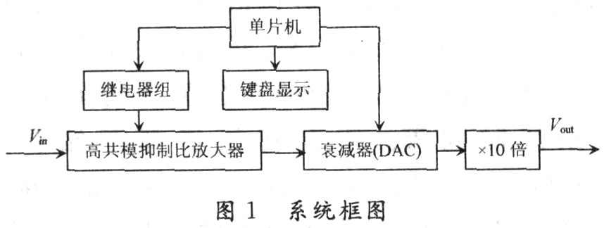
The use of a fixed gain measurement amplifier will inevitably have a great impact on the dynamic performance of the overall amplifier, so this design is mainly composed of three module circuits: a pre-stage high common mode rejection ratio measurement amplifier, an AD7533 attenuator, and a single-chip keyboard display processing module. In the pre-stage high common mode rejection ratio amplifier, the output common mode voltage is fed back to the common end of the positive and negative power supplies to improve the common mode rejection ratio. The attenuator realizes digital programming of the attenuation rate. The single-chip keyboard display processing module controls the 8279 in real time and also digitally controls the AD7533. The overall system block diagram is shown in Figure 1.

From the overall system block diagram, it can be analyzed that the system's amplification factor for the input signal is:
![]()
Among them, Ac is the amplification factor of the pre-amplifier, and ADAC is the attenuation rate of the attenuator.
1.1 Preamplifier
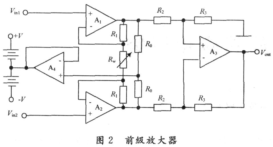
Here, an instrument amplifier is used to form a high common-mode rejection ratio measurement amplifier as shown in Figure 2. Op amp A4 realizes the feedback of the output common-mode voltage to the common end of the power supply, so that the op amp power supply voltage floats with the common-mode input voltage, so that the bias voltage of each level tracks the common-mode input voltage, so that the common-mode signal of each level is greatly weakened, and the error voltage generated by the common-mode input voltage at the output end of the amplifier is greatly reduced, thereby improving the common-mode rejection ratio of the amplifier. In the figure, Rw is composed of three parallel fixed resistance paths, and the three resistance paths are realized by three relays controlled by a single-chip microcomputer. It is easy to analyze that the amplification factor of this amplifier is:
![]()

Therefore, by changing Rw, three control levels of the pre-stage voltage amplification factor are obtained, and the signals of three different voltage segments of 1-10 V, 0.1-1 V and less than 0.1 V are controlled respectively, and different amplification factors are achieved by relay switching, as shown in Table 1.

1.2 MCU and attenuator part
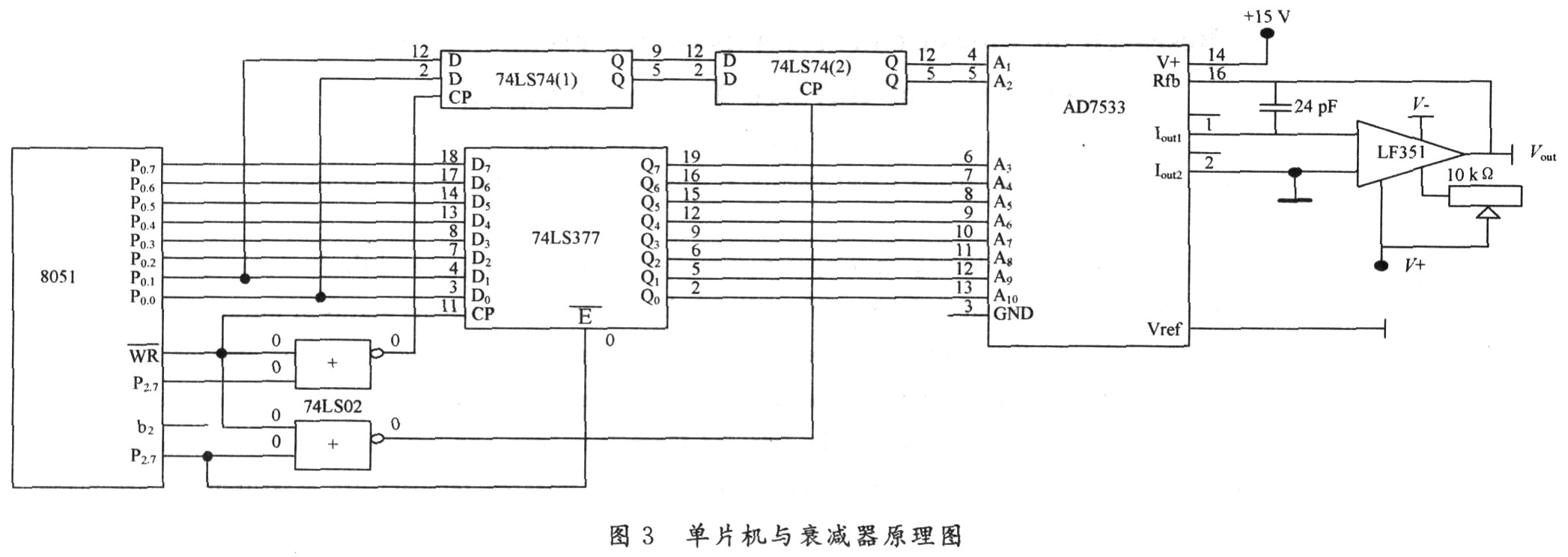
The single-chip microcomputer realizes the overall control and display, and is composed of a 51 single-chip microcomputer and an 8279 keyboard display chip. The number setting can be realized by the 0-9 numeric keys and the control keys such as addition, subtraction, and preset numbers. Any input signal is amplified in the front stage and then multiplied by 10 times by the rear stage programmable attenuator to obtain the final voltage amplification factor. The schematic diagram of the single-chip microcomputer and attenuator is shown in Figure 3.

Under the algorithm control of the single-chip microcomputer, the amplification factor of the pre-stage amplifier is appropriately selected, so that the principle of relay action is: select the minimum pre-stage amplification factor and the corresponding minimum post-stage attenuation rate, so that the error caused by the attenuator of the pre-stage amplifier is as small as possible.
The variable gain attenuator AD7533 is also controlled by a single chip microcomputer. Different 10-bit digital inputs will give different output-input voltage ratios. Adjusting the corresponding attenuation rate will give the corresponding gain. For a 10-bit AD7533, the attenuation will change by 1/1,024 for every 1-bit change in the digital value, achieving a 1,000-fold voltage gain with a step size of 1. For example, when you want to get a voltage gain of 205, just set OCDH (205D) to AD7533 and select the pre-stage gain of 102.4, so you get: 102.4×10×205/1 024=205 gain; when you want to get a voltage gain of 60, just make an attenuation of 600/1 024 and select the pre-stage gain of 10.24, so you get: 10.24×10×600/1 024=60 gain; when you want to get a voltage gain of 6, just make an attenuation of 600/1 024 and select the pre-stage gain of 1.024, so you get: 1.024×10×600/1 024=6 gain.
2 Test Results
According to the above ideas, the amplification factor of the actual measurement amplifier was tested. The corresponding DC signal was input and the results are shown in Table 2.

3 Conclusion
From the test results, it can be seen that the differential mode voltage amplification factor of the measurement amplifier is large, the amplification factor can be preset, and the display is intuitive and convenient. It can meet the requirements of small signal measurement with high precision within the range of 10 V. The amplification amount of the first and second stages can be reasonably allocated according to the preset voltage amplification factor, and the amplification factor preset function of 1 to 1 000 with a step of 1 is realized. At the same time, a variety of improvement measures are adopted to improve the common mode rejection ratio of the amplifier.
Previous article:Implementing a 2.38 GHz Fully Integrated Low Noise Amplifier Using ADS
Next article:Design of a medium-speed and high-precision analog voltage comparator
- High signal-to-noise ratio MEMS microphone drives artificial intelligence interaction
- Advantages of using a differential-to-single-ended RF amplifier in a transmit signal chain design
- ON Semiconductor CEO Appears at Munich Electronica Show and Launches Treo Platform
- ON Semiconductor Launches Industry-Leading Analog and Mixed-Signal Platform
- Analog Devices ADAQ7767-1 μModule DAQ Solution for Rapid Development of Precision Data Acquisition Systems Now Available at Mouser
- Domestic high-precision, high-speed ADC chips are on the rise
- Microcontrollers that combine Hi-Fi, intelligence and USB multi-channel features – ushering in a new era of digital audio
- Using capacitive PGA, Naxin Micro launches high-precision multi-channel 24/16-bit Δ-Σ ADC
- Fully Differential Amplifier Provides High Voltage, Low Noise Signals for Precision Data Acquisition Signal Chain
- Innolux's intelligent steer-by-wire solution makes cars smarter and safer
- 8051 MCU - Parity Check
- How to efficiently balance the sensitivity of tactile sensing interfaces
- What should I do if the servo motor shakes? What causes the servo motor to shake quickly?
- 【Brushless Motor】Analysis of three-phase BLDC motor and sharing of two popular development boards
- Midea Industrial Technology's subsidiaries Clou Electronics and Hekang New Energy jointly appeared at the Munich Battery Energy Storage Exhibition and Solar Energy Exhibition
- Guoxin Sichen | Application of ferroelectric memory PB85RS2MC in power battery management, with a capacity of 2M
- Analysis of common faults of frequency converter
- In a head-on competition with Qualcomm, what kind of cockpit products has Intel come up with?
- Dalian Rongke's all-vanadium liquid flow battery energy storage equipment industrialization project has entered the sprint stage before production
- Allegro MicroSystems Introduces Advanced Magnetic and Inductive Position Sensing Solutions at Electronica 2024
- Car key in the left hand, liveness detection radar in the right hand, UWB is imperative for cars!
- After a decade of rapid development, domestic CIS has entered the market
- Aegis Dagger Battery + Thor EM-i Super Hybrid, Geely New Energy has thrown out two "king bombs"
- A brief discussion on functional safety - fault, error, and failure
- In the smart car 2.0 cycle, these core industry chains are facing major opportunities!
- The United States and Japan are developing new batteries. CATL faces challenges? How should China's new energy battery industry respond?
- Murata launches high-precision 6-axis inertial sensor for automobiles
- Ford patents pre-charge alarm to help save costs and respond to emergencies
- New real-time microcontroller system from Texas Instruments enables smarter processing in automotive and industrial applications
- How smart stores equipped with multiple sensors make shopping a breeze
- Sampling Theorem-------------What is the relationship between the detected signal and the ADC sampling rate?
- Showing off the products + CSR development board 10 years ago, when the Bluetooth market was just beginning to develop!
- LIN communication wake-up question
- An introduction to TI's high-efficiency integrated power supply selection and reference designs
- About the problem of the ambient light sensor of the rsl10-sense-gevk board not working well
- The sine wave signal is distorted after passing through the op amp
- Update summary: justd0 analyzes the official routine of LSM6DSOX finite state machine
- [Summary] A detailed introduction to various power protection circuits
- A 25-year-old DJI employee died suddenly of cardiac arrest, having just graduated with a master's degree

 Introduction to Artificial Intelligence and Robotics (Murphy)
 AUTOSAR MCAL Principles and Practice


 京公网安备 11010802033920号