General LED lighting has a current limiting resistor in the driving circuit, and the power consumed by the resistor has nothing to do with the LED light emission. In order to improve efficiency, a switching power supply with constant current output should be used, and a power MOSFET should be used at the output stage.
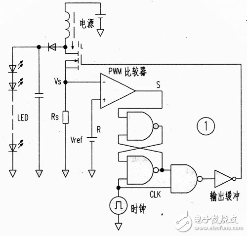
Figure 1 is a block diagram of this drive circuit, which omits the triangular wave generator and error amplifier of the traditional circuit and uses a CMOS logic IC and a PWM modulator. When the clock CLK signal is low, the RS trigger is in a reset state and the output FET is turned off. When the CLK signal is high, the output FET is turned on. Its current is converted into a voltage by the resistor Rs. When this voltage is higher than the reference voltage Vref, the comparator output changes from high to low, the RS trigger is reset again, and the output FET is turned off again. As a result, even if the power supply voltage changes, the energy stored in the inductor is constant. Constant power output is achieved. Here, the voltage drop on Rs is used as a triangular wave voltage, and the PWM comparator directly compares this voltage with the reference voltage and acts as an error amplifier.

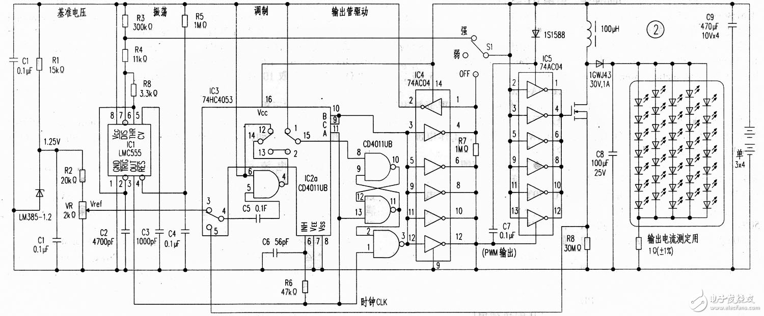
The actual circuit is shown in Figure 2, which is composed of discrete components, with the focus on the PWM comparator and voltage-doubler pulse output circuit.

The PWM comparator is composed of a NAND gate IC2a and an analog switch IC3, which is the so-called chopper comparator. One input of the NAND gate is set to a high level to become an inverter. This inverter repeatedly works in the two states of "precharge" and "compare".
Pre-charge state
In the pre-charge state, capacitor C5 is charged by the reference voltage Vref provided by IC6 (LM385). At this time, the output is neither high level nor low level; it remains in the output state when the comparator is about to flip, and is combined with the ItS trigger to form a PWM circuit.
Comparison Status
The input voltage shifts the voltage level charged on C5 and inputs it to the inverter, where it is compared with the threshold voltage of the inverter and outputs a high or low level.
Voltage doubler pulse output circuit
As the name implies, this is to generate a pulse that is twice the power supply voltage. First, when the input is low level, capacitor C7 is charged and the output is 0V; when the input is high level, the voltage on voc and the capacitor is connected in series, and the voltage at the Y1X) terminal of inverter IC5 is 2Vcc; because the voc voltage is added to the Yss terminal, the output is 2Vcc.
In FIG. 2 , the 555 (IC1) timing circuit generates a clock pulse, and the charging voltage of C2 is changed through the brightness adjustment switch 51 to change the clock frequency by selecting two frequencies of 11.4kHz and 965Hz, so as to achieve the purpose of changing the brightness.
The output circuit and PWM comparator are directly connected to the power supply, but the power consumption is only 10uA when the light is not on.
The output is connected to 35 white light diodes, which are divided into five groups of series and parallel.
Previous article:The introduction of new packaging technologies is accelerating, and the LED backlight market structure may be restructured
Next article:Two very creative LED lamps
- High signal-to-noise ratio MEMS microphone drives artificial intelligence interaction
- Advantages of using a differential-to-single-ended RF amplifier in a transmit signal chain design
- ON Semiconductor CEO Appears at Munich Electronica Show and Launches Treo Platform
- ON Semiconductor Launches Industry-Leading Analog and Mixed-Signal Platform
- Analog Devices ADAQ7767-1 μModule DAQ Solution for Rapid Development of Precision Data Acquisition Systems Now Available at Mouser
- Domestic high-precision, high-speed ADC chips are on the rise
- Microcontrollers that combine Hi-Fi, intelligence and USB multi-channel features – ushering in a new era of digital audio
- Using capacitive PGA, Naxin Micro launches high-precision multi-channel 24/16-bit Δ-Σ ADC
- Fully Differential Amplifier Provides High Voltage, Low Noise Signals for Precision Data Acquisition Signal Chain
- Innolux's intelligent steer-by-wire solution makes cars smarter and safer
- 8051 MCU - Parity Check
- How to efficiently balance the sensitivity of tactile sensing interfaces
- What should I do if the servo motor shakes? What causes the servo motor to shake quickly?
- 【Brushless Motor】Analysis of three-phase BLDC motor and sharing of two popular development boards
- Midea Industrial Technology's subsidiaries Clou Electronics and Hekang New Energy jointly appeared at the Munich Battery Energy Storage Exhibition and Solar Energy Exhibition
- Guoxin Sichen | Application of ferroelectric memory PB85RS2MC in power battery management, with a capacity of 2M
- Analysis of common faults of frequency converter
- In a head-on competition with Qualcomm, what kind of cockpit products has Intel come up with?
- Dalian Rongke's all-vanadium liquid flow battery energy storage equipment industrialization project has entered the sprint stage before production
- Allegro MicroSystems Introduces Advanced Magnetic and Inductive Position Sensing Solutions at Electronica 2024
- Car key in the left hand, liveness detection radar in the right hand, UWB is imperative for cars!
- After a decade of rapid development, domestic CIS has entered the market
- Aegis Dagger Battery + Thor EM-i Super Hybrid, Geely New Energy has thrown out two "king bombs"
- A brief discussion on functional safety - fault, error, and failure
- In the smart car 2.0 cycle, these core industry chains are facing major opportunities!
- The United States and Japan are developing new batteries. CATL faces challenges? How should China's new energy battery industry respond?
- Murata launches high-precision 6-axis inertial sensor for automobiles
- Ford patents pre-charge alarm to help save costs and respond to emergencies
- New real-time microcontroller system from Texas Instruments enables smarter processing in automotive and industrial applications
- Live FAQ|Typical applications in the era of the Internet of Things
- CCS import routine for TM4C123x
- EEWORLD University Hall----Signal Integrity and High-Speed Digital Circuit Design
- Competition Schedule [Updated]
- Output impedance problem of parallel reference voltage
- Master Python web crawler core technology, framework and project practice PDF HD full version free download
- position2Go Review 2: Interlude
- Design of AC voltage measurement based on MSP430 microcontroller
- 【Beetle ESP32-C3】4. Luat-OS environment deployment
- A brief discussion on the differences between x86, DSP and SPARC

 LED Street Light Design 150W Power Supply Design Guide Using FL7930B and FAN7621S


 京公网安备 11010802033920号