The fire control computer is an important part of the entire fire control system. Like the human brain, it is also the intermediate link between the search and tracking system and the weapon aiming system in the fire control system. During combat, the fire control computer receives the target parameters collected by the search and tracking system in real time, completes the real-time calculation of the shooting parameters according to the target's motion trajectory and the ballistic firing table of the configured artillery, and controls the weapon aiming system to effectively shoot at the target. Therefore, the external interface relationship of the fire control computer is relatively complex. This article mainly describes the hardware design of the fire control computer interface circuit in a certain type of fire control system.
1 Design of interface circuit
Since there are many interfaces in this fire control computer and they are of different types, for the sake of ease of description, the interfaces in this system are divided into two categories: communication interface and control interface.
1.1 Communication interface
The communication interfaces in this fire control computer mainly include: (1) a serial port for receiving the azimuth and elevation angle of the current position of this radar or a different radar; (2) a parallel port for receiving parameters such as radar distance, laser distance, radar status, etc. Different interfaces match different interface circuits.
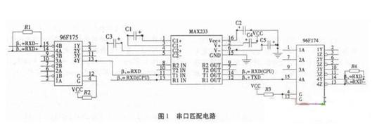
Since the serial port of the main CPU in the fire control computer is a standard RS232 port, it outputs TIA/EIA-232-F level, while the single-chip microcomputer used in the tracking system has a TTL level output, as shown in Figure 1. The serial port matching circuit uses max232 for level conversion. The device contains 2 drivers, 2 receivers and a voltage generator circuit to provide TIA/EIA-232-F level. The device complies with the TIA/EIA-232-F standard. Each receiver converts the TIA/EIA-232-F level into TTL/CMOS level. Each transmitter converts the TTL/CMOS level into TIA/EIA-232-F level. At the same time, in order to ensure the accuracy and reliability of data transmission and improve anti-interference, the receiving signal RX in the serial port is converted into differential form through 96F175 and the transmitting signal TX is converted into differential form through 96F174 before transmission.

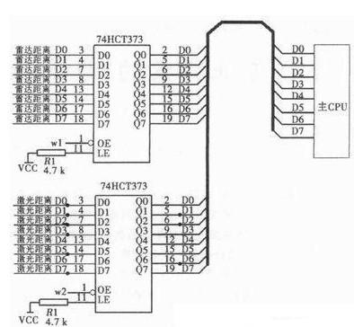
In any combat mode, the main CPU must receive or send different data in real time, that is, there will be multiple sets of data hanging on the 16-bit data bus of the main CPU at the same time, which requires latching the temporarily unneeded data. As shown in Figure 2, the parallel port matching circuit, 74HCT373 is an eight-D latch with three-state output, and the output terminals Q0~Q7 can be directly connected to the bus. When the three-state enable control terminal OE is low, Q0~Q7 is in a normal logic state and can be used to drive the load or bus. When OE is high, Q0~Q7 is in a high-impedance state, neither driving the bus nor being the load of the bus, but the logical operation inside the latch is not affected. When the latch enable terminal LE is high, Q changes with the data D. When LE is low, Q is latched at the established data level.

Figure 2: Parallel port matching circuit
In this circuit, the latch enable terminal LE is fixed at a high level, and the control of the three-state enable control terminal OE is decided by the main CPU. The specific control process is shown in the control interface part.
1.2 Control interface
The control interface mainly includes display control of various status quantities for the convenience of soldiers' operation. The specific display unit is on the operation panel or company command box panel, as well as time-sharing multiplexing control of the data interface.
During the operation, the commanders need to know the various states of the system at any time in order to make correct judgments. Therefore, the fire control computer should indicate various state quantities, such as tracking, searching, presence of elements, absence of elements, echo, point removal, fault and other information to the operator and the company commander in real time. Therefore, the control of display indication is particularly important, and it must be fast and accurate.

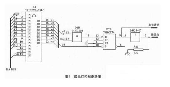
Multiple GAL20V8 chips are used for compilation. GAL decodes and reads different addresses to output W1~W8 for data reading and writing control and indicator light control. Take the control of various element lights as an example, see Figure 3 for the circuit diagram of various element lights control and Figure 2 for the parallel port matching circuit. W1 is used for radar distance reading control. When the main CPU needs to read the radar distance, W1 will be set high, and the data in latch 74HCT373 will be output to the data bus and read by the main CPU; similarly, W2 is used for laser distance reading control. When the main CPU needs to read the laser distance, W2 will be set high. W7 and reset act on the clear end of the trigger 74HCT74 through the AND gate 74HCT08 to control the extinguishing of various element lights; W8 acts on the set end of 74HCT74 to control the lighting of various element lights.
2 Conclusion
The circuit design in this article has been applied in a certain type of fire control computer and has been formally equipped for use by troops. After years of verification, the design of the interface circuit is feasible, reliable, and has good reference value.
Previous article:IDT Creates First New Quad-Channel DAC with JESD204B Interface
Next article:High-performance architecture implementation technology for frequency synthesizers
- Popular Resources
- Popular amplifiers
-
 Computer Vision Applications in Autonomous Vehicles: Methods, Challenges, and Future Directions
 -
 Hardware Accelerators in Autonomous Driving
 -
 Computer Vision for Driver Assistance: Simultaneously Monitoring Traffic and the Driver
 -
 Deep Learning Computer Vision: Neural Network Architectures Using Python and Keras
- High signal-to-noise ratio MEMS microphone drives artificial intelligence interaction
- Advantages of using a differential-to-single-ended RF amplifier in a transmit signal chain design
- ON Semiconductor CEO Appears at Munich Electronica Show and Launches Treo Platform
- ON Semiconductor Launches Industry-Leading Analog and Mixed-Signal Platform
- Analog Devices ADAQ7767-1 μModule DAQ Solution for Rapid Development of Precision Data Acquisition Systems Now Available at Mouser
- Domestic high-precision, high-speed ADC chips are on the rise
- Microcontrollers that combine Hi-Fi, intelligence and USB multi-channel features – ushering in a new era of digital audio
- Using capacitive PGA, Naxin Micro launches high-precision multi-channel 24/16-bit Δ-Σ ADC
- Fully Differential Amplifier Provides High Voltage, Low Noise Signals for Precision Data Acquisition Signal Chain
- Innolux's intelligent steer-by-wire solution makes cars smarter and safer
- 8051 MCU - Parity Check
- How to efficiently balance the sensitivity of tactile sensing interfaces
- What should I do if the servo motor shakes? What causes the servo motor to shake quickly?
- 【Brushless Motor】Analysis of three-phase BLDC motor and sharing of two popular development boards
- Midea Industrial Technology's subsidiaries Clou Electronics and Hekang New Energy jointly appeared at the Munich Battery Energy Storage Exhibition and Solar Energy Exhibition
- Guoxin Sichen | Application of ferroelectric memory PB85RS2MC in power battery management, with a capacity of 2M
- Analysis of common faults of frequency converter
- In a head-on competition with Qualcomm, what kind of cockpit products has Intel come up with?
- Dalian Rongke's all-vanadium liquid flow battery energy storage equipment industrialization project has entered the sprint stage before production
- Allegro MicroSystems Introduces Advanced Magnetic and Inductive Position Sensing Solutions at Electronica 2024
- Car key in the left hand, liveness detection radar in the right hand, UWB is imperative for cars!
- After a decade of rapid development, domestic CIS has entered the market
- Aegis Dagger Battery + Thor EM-i Super Hybrid, Geely New Energy has thrown out two "king bombs"
- A brief discussion on functional safety - fault, error, and failure
- In the smart car 2.0 cycle, these core industry chains are facing major opportunities!
- The United States and Japan are developing new batteries. CATL faces challenges? How should China's new energy battery industry respond?
- Murata launches high-precision 6-axis inertial sensor for automobiles
- Ford patents pre-charge alarm to help save costs and respond to emergencies
- New real-time microcontroller system from Texas Instruments enables smarter processing in automotive and industrial applications
- Top 5 most popular blog posts in 2019 - Helping 5G development
- DDS signal source based on FPGA
- Integer square root algorithm
- Combining the new 6-axis IMU with DSP to achieve high-performance motion tracking accuracy
- Six design issues for I2C isolators
- Common problems and solutions in CCS compilation
- Can TVS be used to extinguish arcs?
- #SpaceX sends 4 civilians into space#When can I travel in space too???
- The problem of via aperture and line width
- Use one data line to control full-color LED lights! Single bus LED usage guide

 Computer Vision Applications in Autonomous Vehicles: Methods, Challenges, and Future Directions


 京公网安备 11010802033920号