In technology fields such as medical equipment, automotive instrumentation, and industrial control, when equipment design involves strain gauges, sensor interfaces, and current monitoring, precision analog front-end amplifiers are often required to extract and amplify very weak real signals and suppress unwanted signals such as common-mode voltage and noise. Initially, designers will focus on ensuring that precision parameters such as device-level noise, offset, gain, and temperature stability meet application requirements.
Designers can then select front-end analog components that meet the total error budget requirements based on the above characteristics. However, there is an often overlooked problem in such applications, which is high-frequency interference caused by external signals, which is commonly known as "electromagnetic interference (EMI)". EMI can occur in many ways, mainly affected by the end application. For example, an instrumentation amplifier may be used in a control board that interfaces with a DC motor. The motor's current loop, which includes power leads, brushes, commutator, and coils, usually acts like an antenna and can emit high-frequency signals, which may interfere with the tiny voltage at the input of the instrumentation amplifier.
Another example is current sensing in automotive solenoid control. The solenoid is powered from the vehicle battery through long wires that act like antennas. A series shunt resistor is connected in the wire path, and the voltage across the resistor is measured by a current sense amplifier. High-frequency common-mode signals may exist in the line, and the input of the amplifier is susceptible to such external signals. Once affected by external high-frequency interference, the accuracy of the analog device may be degraded, and it may even be impossible to control the solenoid circuit. This state manifests in the amplifier as the amplifier output accuracy exceeds the error budget and data sheet tolerance, and in some cases may even reach the limit, causing the control loop to shut down.
How does EMI cause large DC deviations? It may be one of the following situations: Many instrumentation amplifiers are designed to have excellent common-mode rejection performance in the frequency range up to tens of kilohertz. However, when an unshielded amplifier is exposed to RF radiation in the tens or hundreds of "megahertz", problems may arise. At this time, the input stage of the amplifier may experience asymmetrical rectification, resulting in a DC offset that can be very significant after further amplification, and combined with the gain of the amplifier, it may even reach the upper limit of its output or some external circuits.
Examples of How High-Frequency Signals Affect Analog Devices
This example will detail a typical high-side current sensing application. Figure 1 shows a common configuration used to monitor solenoid valves or other inductive loads in an automotive environment.
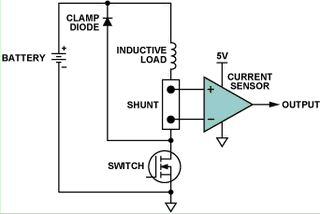
Figure 1. High-side current monitoring.
The effects of high-frequency interference were investigated using two current-sense amplifier configurations of similar design. The two devices are identical in functionality and pinout; however, one has an internal EMI filter circuit while the other does not.
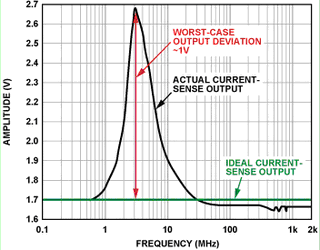
Figure 2. Current sensor output (no internal EMI filter, forward power = 12 dBm, 100 mV/div, DC output peak at 3 MHz)
Figure 2 shows how the DC output of the current sensor deviates from its ideal value when the input varies over a wide frequency range. It can be seen that the deviation is most significant (>0.1 V) in the frequency range of 1 MHz to 20 MHz, and the DC error reaches a maximum value (1 V) at 3 MHz, which accounts for a large proportion of the amplifier's output voltage range of 0 V to 5 V.
Figure 3 shows the test results of the same experiment and configuration using an alternative pin-compatible current sensor with the same circuit architecture and similar DC specifications as the previous example, but with input EMI filtering built in. Note that the voltage range is increased by a factor of 20.
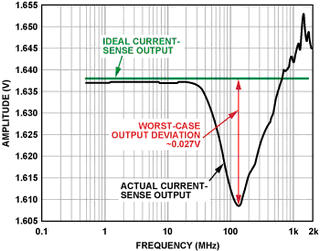
Figure 3. Current sensor output (internal EMI filter, forward power = 12 dBm, 5 mV/div, DC output peaks at >100 MHz)
In this case, the error is only about 3 mV at 40 MHz, and the peak error (at >100 MHz) is less than 30 mV, a 35x improvement. This clearly shows that built-in EMI filtering helps significantly protect the current sensor from high-frequency signals present at the input. In a real-world application, even if the severity of the EMI is unknown, the control loop will actually stay within its tolerance if the current sensor with built-in EMI filtering is used.
Both devices were tested under exactly the same conditions. The only difference is that the AD8208 (see Appendix) has internal low-pass RF input filters on both the input and supply pins. Adding such a component to the chip may seem trivial, but since the application is typically PWM controlled, the current sense amplifier must be able to withstand continuous switching common-mode voltages of up to 45 V. Therefore, the input filters must be closely matched to maintain accurate high gain and common-mode rejection.
Why and how to ensure EMI compliance when designing and testing
Automotive applications are particularly sensitive to EMI events, which are unavoidable in a noisy electrical environment consisting of a central battery, bundled wiring harnesses, various inductive loads, antennas, and external interference associated with the vehicle. Since multiple critical function controls such as airbag deployment, cruise control, braking, and suspension involve electronic devices, EMI compatibility must be guaranteed and no false alarms or false triggers due to external interference are allowed. In the past, EMI compatibility testing was the last test in automotive applications. If something went wrong, designers had to find a solution in a hurry, which often involved changing the board layout, adding additional filters, or even replacing components.
This uncertainty greatly increases design costs and causes a lot of headaches for engineers. The automotive industry has been taking concrete steps to improve EMI compatibility. Because devices must meet EMI standards, automotive OEMs now require semiconductor manufacturers (such as Analog Devices) to perform EMI testing at the device level before considering using their devices. This process is now commonplace, and all IC manufacturers use standard specifications to test the EMI compatibility of their devices.
To learn about the standard EMI test requirements for various types of integrated circuits, please purchase documents from the International Electrotechnical Commission (IEC). Documents such as IEC 62132 and IEC 61967 provide information about EMI and EMC, which describe in great detail how to test specific integrated circuits using industry-recognized standards. The various tests mentioned above are performed according to these guidelines.
Specifically, these tests are done using “direct power injection,” a method that couples RF signals to specific device pins through capacitors. Depending on the type of IC being tested, each input of the device is tested for different RF signal power levels and frequency ranges. Figure 4 shows a schematic diagram of how direct power injection testing is performed on specific pins.
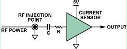
Figure 4. Direct power injection
These standards contain a great deal of necessary information on circuit configuration, layout methods, and monitoring techniques to help properly understand the success or failure of device testing. A more complete schematic of the IEC standard is shown in Figure 5.
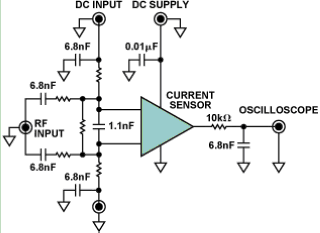
Figure 5. EMI tolerance test schematic
Summarize
EMI compatibility of integrated circuits is critical to the success of electronic designs. This article shows how two very similar amplifiers can perform dc measurements in an RF environment with or without an internal EMI filter. EMI is a very important aspect of automotive applications when considering safety and reliability. Today, IC manufacturers such as Analog Devices are increasingly considering EMI tolerance when designing and testing devices for critical applications. IEC standards provide useful guidelines in great detail. For the automotive market, current sensing devices such as the AD8207, AD8208, and AD8209 have passed EMI testing. Newer devices such as the AD8280 lithium-ion battery safety monitor and the AD8556 digitally programmable sensor signal amplifier have been designed and tested to meet EMI requirements.
Previous article:Operational Amplifier Design Principles
Next article:Analog and digital filters
Recommended ReadingLatest update time:2024-11-16 22:48


- Popular Resources
- Popular amplifiers
-
 Study on the Behavioral Model of Silicon Carbide MOSFET Power Module and EMI Prediction of Low-Voltage Auxiliary Power Supply
 -
 Cable radiated EMI modeling considering mutual coupling effects_Junpeng Ji
 -
 Design of broadband hybrid active EMI filter for switching power supply_Liao Yuehong
 -
 Switching power supply conducted EMI simulation and filter circuit design_Jiang Yunfu
- High signal-to-noise ratio MEMS microphone drives artificial intelligence interaction
- Advantages of using a differential-to-single-ended RF amplifier in a transmit signal chain design
- ON Semiconductor CEO Appears at Munich Electronica Show and Launches Treo Platform
- ON Semiconductor Launches Industry-Leading Analog and Mixed-Signal Platform
- Analog Devices ADAQ7767-1 μModule DAQ Solution for Rapid Development of Precision Data Acquisition Systems Now Available at Mouser
- Domestic high-precision, high-speed ADC chips are on the rise
- Microcontrollers that combine Hi-Fi, intelligence and USB multi-channel features – ushering in a new era of digital audio
- Using capacitive PGA, Naxin Micro launches high-precision multi-channel 24/16-bit Δ-Σ ADC
- Fully Differential Amplifier Provides High Voltage, Low Noise Signals for Precision Data Acquisition Signal Chain
- Innolux's intelligent steer-by-wire solution makes cars smarter and safer
- 8051 MCU - Parity Check
- How to efficiently balance the sensitivity of tactile sensing interfaces
- What should I do if the servo motor shakes? What causes the servo motor to shake quickly?
- 【Brushless Motor】Analysis of three-phase BLDC motor and sharing of two popular development boards
- Midea Industrial Technology's subsidiaries Clou Electronics and Hekang New Energy jointly appeared at the Munich Battery Energy Storage Exhibition and Solar Energy Exhibition
- Guoxin Sichen | Application of ferroelectric memory PB85RS2MC in power battery management, with a capacity of 2M
- Analysis of common faults of frequency converter
- In a head-on competition with Qualcomm, what kind of cockpit products has Intel come up with?
- Dalian Rongke's all-vanadium liquid flow battery energy storage equipment industrialization project has entered the sprint stage before production
- Allegro MicroSystems Introduces Advanced Magnetic and Inductive Position Sensing Solutions at Electronica 2024
- Car key in the left hand, liveness detection radar in the right hand, UWB is imperative for cars!
- After a decade of rapid development, domestic CIS has entered the market
- Aegis Dagger Battery + Thor EM-i Super Hybrid, Geely New Energy has thrown out two "king bombs"
- A brief discussion on functional safety - fault, error, and failure
- In the smart car 2.0 cycle, these core industry chains are facing major opportunities!
- The United States and Japan are developing new batteries. CATL faces challenges? How should China's new energy battery industry respond?
- Murata launches high-precision 6-axis inertial sensor for automobiles
- Ford patents pre-charge alarm to help save costs and respond to emergencies
- New real-time microcontroller system from Texas Instruments enables smarter processing in automotive and industrial applications
- RT Thread IPC Summary
- Analysis of 5G millimeter wave terminal technology and test solutions
- 07. Anlu SparkRoad domestic FPGA evaluation [Learning] Serial port loopback experiment
- Pseudo-random sequence principle.pdf
- What is the working principle of pneumatic solenoid valve? What are the classifications of pneumatic solenoid valves?
- [SC8905 EVM Evaluation] + I2C communication between MCU and SC8905
- [RVB2601 Creative Application Development] 2 Familiar with basic peripherals GPIO
- [2022 Digi-Key Innovation Design Competition] Deploy blockchain smart contracts
- [AT32F421 Review] + Digital tube module and automatic counting display
- Today's broadcast starts at 10:00: Focus on "TI FPD-Link III automotive chipset", the ideal solution for automotive video transmission

 Study on the Behavioral Model of Silicon Carbide MOSFET Power Module and EMI Prediction of Low-Voltage Auxiliary Power Supply


 京公网安备 11010802033920号