The circuit in this design generates a zero-crossing pulse of the AC mains and provides electrical isolation. The falling edge of the output pulse occurs about 200μs before the zero-crossing point. This circuit can be used to safely stop the triggering of a thyristor gate, giving it time to shut down properly. The circuit only generates short pulses when the mains voltage is about 0V, so it consumes only 200mW at 230V, 50Hz input.
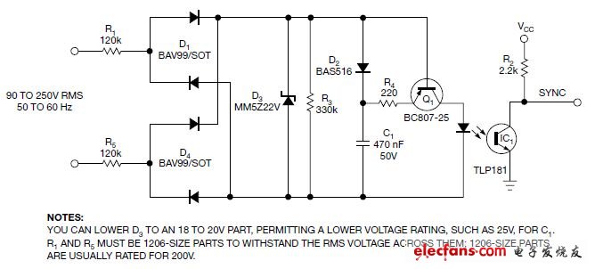
The circuit charges capacitor C1 until it reaches the upper limit of 22V Zener diode D3 (Figure 1 and Reference 1). Resistors R1 and R5 limit the input current. When the input rectified voltage drops below the voltage of C1, Q1 begins to conduct, generating a pulse several hundred microseconds long. The coupling of IC1 causes Q1's square wave generator to respond. Only R1 and R5 are required for rms operating voltage. SMD 1206-type resistors can generally withstand 200V rms. This design divides the input voltage in half between R1 and R5, giving a total voltage rating of 400V rms. D3 limits the bridge voltage to 22V, so all subsequent components have lower voltage ratings. The 22V Zener can clamp to 30V, so this design uses a 50V, 470nF ceramic capacitor. Ceramic capacitors have better reliability than electrolytic or tantalum capacitors, especially at high temperatures. If you prefer to use cheaper and smaller 25V components, you can change the Zener voltage to 18V and still have a good safety margin. R4 is used to limit the peak current in the LED. The main limitation on the LED current is the slope of the rectified AC input. A slow slope prevents Q1 from producing a current spike when C1 releases the stored energy.

Figure 1. This zero-crossing detector uses low-voltage components and consumes very little power.
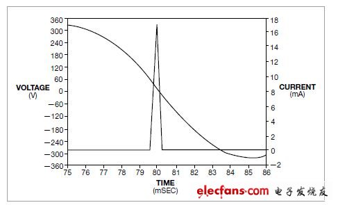
The operation of this circuit can be simulated in LTspice Version IV (Figure 2 and Reference 2). At 230V, 50Hz, the simulation shows a 17mA peak across the optocoupler LED. The simulation gives good results for inputs from 90V to 250V (50Hz and 60Hz). At 110V, 60Hz input, the LED current peaks at 8.5mA, so IC1 still works. If higher LED drive current is needed, the value of R3 can be reduced, or the value of C1 can be increased.

Figure 2. This is an LTspice simulation. When the input voltage drops below 0V, the LED current generates a pulse with edges leading and lagging the crossover point. The peak current of the optocoupler LED is 17mA.

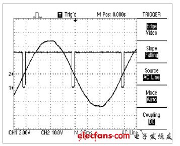
Figure 3. The results of the prototype circuit correlate well with the simulation.
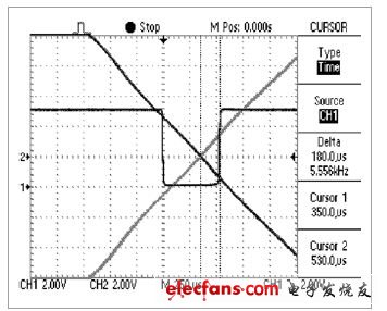
Testing of an actual circuit shows good correlation with simulation (Figure 3). Using a 5V logic supply to drive the isolated outputs, a good pulse waveform is obtained (Trace 1). For safety, the main input is fed to the oscilloscope through a 15V isolation transformer (Trace 2). The zero crossing points of the transition can be shown using the oscilloscope's persistence feature (Figure 4). This approach allows accurate measurement of the timing of the pulses relative to the input zero crossings.

Figure 4. Using the persistence function of an oscilloscope, the exact zero crossing is shown.
Previous article:TER Yaw Cable Counter Principle
Next article:RFC circuit design and analysis
- Popular Resources
- Popular amplifiers
- High signal-to-noise ratio MEMS microphone drives artificial intelligence interaction
- Advantages of using a differential-to-single-ended RF amplifier in a transmit signal chain design
- ON Semiconductor CEO Appears at Munich Electronica Show and Launches Treo Platform
- ON Semiconductor Launches Industry-Leading Analog and Mixed-Signal Platform
- Analog Devices ADAQ7767-1 μModule DAQ Solution for Rapid Development of Precision Data Acquisition Systems Now Available at Mouser
- Domestic high-precision, high-speed ADC chips are on the rise
- Microcontrollers that combine Hi-Fi, intelligence and USB multi-channel features – ushering in a new era of digital audio
- Using capacitive PGA, Naxin Micro launches high-precision multi-channel 24/16-bit Δ-Σ ADC
- Fully Differential Amplifier Provides High Voltage, Low Noise Signals for Precision Data Acquisition Signal Chain
- Innolux's intelligent steer-by-wire solution makes cars smarter and safer
- 8051 MCU - Parity Check
- How to efficiently balance the sensitivity of tactile sensing interfaces
- What should I do if the servo motor shakes? What causes the servo motor to shake quickly?
- 【Brushless Motor】Analysis of three-phase BLDC motor and sharing of two popular development boards
- Midea Industrial Technology's subsidiaries Clou Electronics and Hekang New Energy jointly appeared at the Munich Battery Energy Storage Exhibition and Solar Energy Exhibition
- Guoxin Sichen | Application of ferroelectric memory PB85RS2MC in power battery management, with a capacity of 2M
- Analysis of common faults of frequency converter
- In a head-on competition with Qualcomm, what kind of cockpit products has Intel come up with?
- Dalian Rongke's all-vanadium liquid flow battery energy storage equipment industrialization project has entered the sprint stage before production
- Allegro MicroSystems Introduces Advanced Magnetic and Inductive Position Sensing Solutions at Electronica 2024
- Car key in the left hand, liveness detection radar in the right hand, UWB is imperative for cars!
- After a decade of rapid development, domestic CIS has entered the market
- Aegis Dagger Battery + Thor EM-i Super Hybrid, Geely New Energy has thrown out two "king bombs"
- A brief discussion on functional safety - fault, error, and failure
- In the smart car 2.0 cycle, these core industry chains are facing major opportunities!
- The United States and Japan are developing new batteries. CATL faces challenges? How should China's new energy battery industry respond?
- Murata launches high-precision 6-axis inertial sensor for automobiles
- Ford patents pre-charge alarm to help save costs and respond to emergencies
- New real-time microcontroller system from Texas Instruments enables smarter processing in automotive and industrial applications
- Why do voice chips have malfunctions?
- consult
- MSP430 timer is set to 1S
- Wi-Fi in 2025: It might be watching your every move
- Please tell me about low noise broadband op amp
- Keil development environment construction
- MSP430 MCU GPIO Demonstration Program
- How much does the parallel import Nokia 3250 cost?
- Which teacher would like to talk about CPL?
- Live review: Infineon BMS solutions protect electric vehicles and energy storage systems!

 Driver Assistance Systems Brochure: Basic information, components and systems for active safety and comfort
 ICCV2023 Paper Summary: Biometrics


 京公网安备 11010802033920号