introduction
The nuclear energy spectrum amplifier is an important part of the energy spectrum measurement system, and its performance directly affects the resolution of the entire energy spectrum measurement system. This paper improves the shortcomings of the traditional nuclear energy spectrum signal amplifier. A universal nuclear energy spectrum signal amplifier with programmable amplification factor is designed and developed, so that it can be used in nuclear energy spectrum measurement instruments such as X-ray fluorescence instrument and gamma spectrometer at the same time, and has universality. If the amplifier further integrates signal acquisition (A/D conversion) technology and digital signal processing (DSP) technology, it can constitute a fully functional nuclear energy spectrum signal processing system.
1 Basic circuit components
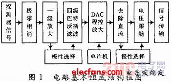
The circuit mainly includes three parts: filter shaping, program-controlled amplification, and baseline elimination. The filter shaping circuit includes pole-zero phase cancellation, four-stage Butterworth filter circuit, and polarity selection circuit; the program-controlled amplification circuit includes a first-stage 20-fold amplification and a 12-bit DAC program-controlled amplification circuit; the baseline elimination circuit includes a DC removal circuit, an inverting circuit, and a voltage follower circuit. The structural block diagram is shown in Figure 1.
2 Unit Circuit Principle Analysis
2.1 Pole-zero cancellation
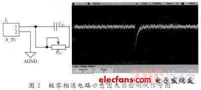
Connecting the pole-zero phase cancellation circuit to the signal input terminal can eliminate the downstroke caused by differentiating the probe signal, making the pulse return to the baseline monotonically. It improves the effects of count rate overload and pulse amplitude superposition, and is suitable for high-resolution and high-count rate spectrometer systems. Figure 2 shows the designed circuit and experimental test signal diagram.
2.2 Filter shaping
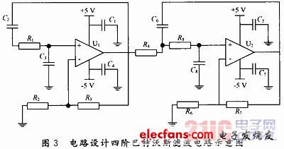
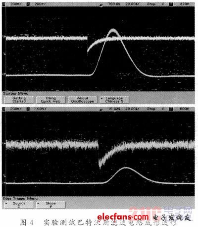
The circuit uses two second-order Butterworth filter circuits cascaded into a fourth-order Butterworth filter circuit. The second-order low-pass Butterworth filter circuit designed with an operational amplifier is directly obtained by using the frequency domain analysis method:
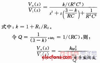
In the formula: k is equivalent to the voltage gain of the common-mode amplifier, which is called the passband gain of the filter; Q is the quality factor; ω0 is the characteristic angular frequency. Figure 3 is the design principle diagram of the filter shaping circuit, and Figure 4 is the experimental test results.
This circuit uses two parts: a first-stage 100-fold fixed amplification and a DAC programmable multiple amplification. The first-stage amplification uses operational amplifier positive feedback. The DAC programmable multiple amplification part controls the 12-bit high-speed DAC chip through a single-chip microcomputer, and uses the DAC's internal precision resistor network as the operational amplifier's feedback resistor to improve the amplification accuracy and achieve 1 to 1,000 times programmable amplification. Output voltage:

Wherein, the value range of D is 0 to 4 095.
The DAC programmable amplifier circuit is shown in Figure 5.

2.4 Baseline elimination
The baseline elimination circuit first inputs the shaped nuclear pulse signal into a first-order low-pass filter circuit to extract the DC component, and then subtracts it from the original signal to remove the DC component. The circuit implementation is shown in Figure 6.

3 Main performance indicators
After the programmable nuclear energy spectrum signal amplifier circuit designed in this paper has been made into a board, welded, and debugged, the power supply adopts a 7-20 V regulated power supply, and the circuit converts it to the required +5 V, -5 V. The signal input end passes through the pole-zero cancellation circuit. After debugging, the R and C values are changed according to the frequency requirements of different inputs (X fluorescence and gamma rays) to achieve pole-zero cancellation. The subsequent first-stage amplification and shaping filtering of the nuclear signal are connected. The output signal is a quasi-Gaussian waveform with a flat top of the pulse. The DAC is controlled by a single-chip microcomputer. After testing, the programmable signal is amplified by 0 to 100 times, which fully realizes the design requirements. Figure 7 is the final test output waveform.

4 Conclusion
The programmable nuclear energy spectrum signal amplifier designed in this paper has been analyzed and designed, and the circuit board, welding and debugging have been proved by experiments to meet the design requirements of filtering and shaping the energy spectrum signal and 0-100 times programmable amplification. This design can be used in X-ray fluorescence and gamma spectrum measurement systems, achieving the versatility and flexibility of the design requirements. Compared with traditional nuclear signal amplification and shaping, the programmable signal amplifier designed in this paper also has the advantages of low power consumption and easy hardware miniaturization, meeting the design requirements of modern nuclear signal processing.
Previous article:Noise Countermeasure Basics (Part 3): Principles of Noise Filters
Next article:Briefly introduce the working principle and characteristics of the oscillation circuit
- Popular Resources
- Popular amplifiers
-
 Nuclear Magnetic Resonance (NMR) Spectroscopy for the In Situ Measurement of Vapor−Liquid Equilibria
 -
 Wireless Communication Electronics:Introduction to RF Circuits and Design...
 -
 Radio Frequency Integrated Circuit PPT (Tian Qingcheng, Department of Electrical Engineering, Chinese University, Taiwan)
 -
 Measuring 2nV/√Hz Noise and 120dB Power Supply Rejection on a Linear Regulator
- High signal-to-noise ratio MEMS microphone drives artificial intelligence interaction
- Advantages of using a differential-to-single-ended RF amplifier in a transmit signal chain design
- ON Semiconductor CEO Appears at Munich Electronica Show and Launches Treo Platform
- ON Semiconductor Launches Industry-Leading Analog and Mixed-Signal Platform
- Analog Devices ADAQ7767-1 μModule DAQ Solution for Rapid Development of Precision Data Acquisition Systems Now Available at Mouser
- Domestic high-precision, high-speed ADC chips are on the rise
- Microcontrollers that combine Hi-Fi, intelligence and USB multi-channel features – ushering in a new era of digital audio
- Using capacitive PGA, Naxin Micro launches high-precision multi-channel 24/16-bit Δ-Σ ADC
- Fully Differential Amplifier Provides High Voltage, Low Noise Signals for Precision Data Acquisition Signal Chain
- Innolux's intelligent steer-by-wire solution makes cars smarter and safer
- 8051 MCU - Parity Check
- How to efficiently balance the sensitivity of tactile sensing interfaces
- What should I do if the servo motor shakes? What causes the servo motor to shake quickly?
- 【Brushless Motor】Analysis of three-phase BLDC motor and sharing of two popular development boards
- Midea Industrial Technology's subsidiaries Clou Electronics and Hekang New Energy jointly appeared at the Munich Battery Energy Storage Exhibition and Solar Energy Exhibition
- Guoxin Sichen | Application of ferroelectric memory PB85RS2MC in power battery management, with a capacity of 2M
- Analysis of common faults of frequency converter
- In a head-on competition with Qualcomm, what kind of cockpit products has Intel come up with?
- Dalian Rongke's all-vanadium liquid flow battery energy storage equipment industrialization project has entered the sprint stage before production
- Allegro MicroSystems Introduces Advanced Magnetic and Inductive Position Sensing Solutions at Electronica 2024
- Car key in the left hand, liveness detection radar in the right hand, UWB is imperative for cars!
- After a decade of rapid development, domestic CIS has entered the market
- Aegis Dagger Battery + Thor EM-i Super Hybrid, Geely New Energy has thrown out two "king bombs"
- A brief discussion on functional safety - fault, error, and failure
- In the smart car 2.0 cycle, these core industry chains are facing major opportunities!
- The United States and Japan are developing new batteries. CATL faces challenges? How should China's new energy battery industry respond?
- Murata launches high-precision 6-axis inertial sensor for automobiles
- Ford patents pre-charge alarm to help save costs and respond to emergencies
- New real-time microcontroller system from Texas Instruments enables smarter processing in automotive and industrial applications
- 【GD32E231 DIY Contest】3. Light up a row of digital tubes
- PCB wiring - signal line crosstalk
- Inductor voltage issues in different topologies
- HuaDa HC32F003 / HC32F005 project template
- RTT & Renesas high-performance CPK-RA6M4 development board evaluation - PWM breathing light and output square wave
- Programmer's tool, embedded artifact ---- Vim
- IL0389 Electronic Paper (Ink Screen) Driver
- Please advise: What is the impact of wireless modules working in a wide voltage range?
- [Perf-V Review] + First Look at Pengfeng Artix 7 FPGA Development Kit
- Can a 0805 SMD LED be lit with a current of 1.25mA?

 Nuclear Magnetic Resonance (NMR) Spectroscopy for the In Situ Measurement of Vapor−Liquid Equilibria
 Radio Frequency Integrated Circuit PPT (Tian Qingcheng, Department of Electrical Engineering, Chinese University, Taiwan)


 京公网安备 11010802033920号