In digital signal processing, discrete Fourier transform (DFT) is a commonly used transform method, which plays an important role in various digital signal processing systems. Fast Fourier transform (FFT) [1-2] is a fast algorithm of discrete Fourier transform. It is obtained by improving the algorithm of discrete Fourier transform based on the odd, even, imaginary and real characteristics of discrete Fourier transform. Both are for transforming signals into frequency domain and performing corresponding spectrum analysis. For signal processing with strong real-time requirements, the impact of operation speed on the entire processing is obvious. Because FFT has high computing power, it is widely used in wireless communication and digital communication, high-speed image processing, matched filtering and other fields.
LTE is a quasi-4G technology based on Orthogonal Frequency Division Multiplexing (OFDM) and Multiple Input Multiple Output (MIMO) technologies. It uses Orthogonal Frequency Division Multiple Access (OFDM) for downlink and Single Carrier Frequency Division Multiple Access (SC-FDMA) for uplink. It can provide peak rates of 100 Mb/s for downlink and 50 Mb/s for uplink in a 20 MHz spectrum bandwidth[3].
Frequency domain analysis is superior to time domain analysis in that it is simple and easy to analyze complex signals[4]. In LTE systems, the FFT algorithm is mainly used in baseband signal generation, signal reception and detection, etc., to transfer time domain signals to the frequency domain for processing.
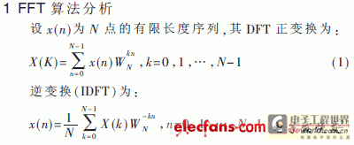
Among them, x(n) is a complex sequence, WNkn and X(K) are also complex numbers, so each calculation of an X(K) value requires N complex multiplication operations and N-1 complex addition operations. Since X(K) has N points in total, it takes N2 complex multiplications and N(N-1) complex addition operations to complete the entire DFT operation. When N is very large, the amount of calculation is considerable. However, for signal processing with strong real-time performance, if the requirements are met, the operation speed will be too high. By using the symmetry, periodicity and reducibility of the rotation factor WNkn, some items in the DFT operation can be merged, and the DFT of a long sequence can be decomposed into several DFTs of short sequences, thereby greatly reducing the number of operations. FFT algorithms can be divided into two categories: time extraction method and frequency domain extraction method. The operational characteristics of the frequency domain extraction method are basically the same as those of the time extraction method. The difference is that the butterfly operation of the frequency domain extraction method is addition first and then multiplication, while the butterfly operation of the time extraction method is multiplication first and then addition; the input sequence of the frequency domain extraction is in natural order, and the output sequence is in reverse order, while the input sequence of the time extraction method is in reverse order and the output sequence is in natural order.
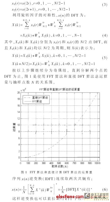
Assume that the length of the input sequence x(n) is N=2M, where M is a positive integer. If this condition is not met, artificially add a number of zero points at the end of the sequence to make it meet this requirement. Decompose the sequence x(n) into two subsequences of N/2 points according to the parity of n:
2 DSP Implementation of FFT Algorithm
2.1 Hardware
The TMS320C6000 series DSP is a high-performance DSP introduced by TI, which combines the advantages of high cost performance and low power consumption. The TMS320C64 series has increased the clock frequency and adopted the VelociTI very long instruction set VLIW (Very Long Instruction Word) structure [5] in terms of architecture. The chip has 8 independent functional unit cores, which can execute 8 32-bit instructions in parallel per cycle, with a maximum peak speed of 4800 MIPS. There are 2 groups of 64 32-bit general registers with a 32-bit addressing range, supporting 8/16/32/40-bit data access. The chip integrates a large-capacity SRAM with a maximum capacity of 8Mb. Due to its excellent computing power, efficient instruction set, and wide-range addressing capability, it is particularly suitable for applications such as wireless base stations and test instruments that require high computing power and storage capacity.
2.2 DSP Implementation of FFT Algorithm
The FFT algorithm is a sub-function module and the input sequence length is different, so the scheme defines the input and output variables and their calling format. Calling format: Turbo_Code (int*, int, int, char*, char*, int*), where int represents the length of the input sequence and the number of FFT levels; int* represents the first address of the input sequence and the first address of the output sequence; char* represents the first address of the cosine of the rotation factor and the first address of the sine of the rotation factor.
The specific implementation process of the FFT algorithm is as follows:
(1) In the time-sampling FFT, the input and output data nodes of each butterfly are on a horizontal line, so the output data of each butterfly can be immediately stored in the storage unit occupied by the original input data. This in-situ calculation can save a lot of memory and theoretically reduce the time to access data between different registers.
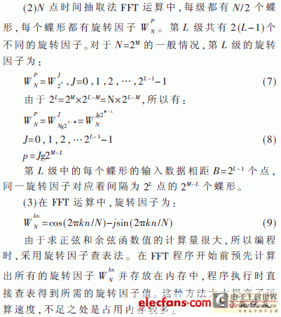
The main function is written in C language, and the implementation function of the FFT algorithm is written in assembly language. The program assumes that the maximum length of the input data is 1024. Since the DSP C6455 can directly access and process 32 bits, a length of 8192 bits is defined in the memory as the memory space for storing the output sequence. In order to improve the accuracy of the calculation, the real and imaginary parts of the input number occupy one word respectively. The assembly instruction MPYHI is used to perform complex multiplication operations in the program. The memory defines a Tempsequence of 2048 bits as the storage of the reverse sequence, and establishes two rotation factor lookup tables, namely Wr and Wi.
In the outer loop, before each inner loop, 32 bits are taken from the input bit sequence and put into a register as the input of an inner loop. After the inner loop ends, the next 32 bits of input are taken to update the register.
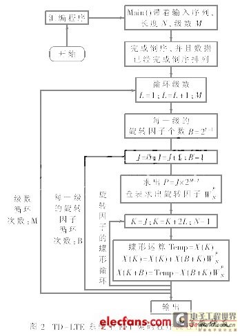
In the inner loop, the butterfly process is calculated by table lookup. For each level, the number of rotation factors required and the interval between the same rotation factors are calculated. When calculating the butterfly process, first extract X(k), and find X(k+B) based on the same rotation factor interval to complete the butterfly calculation. Considering the symmetry of the rotation factors, only half of the rotation factors are stored in the memory, and the remaining data is processed according to the symmetry. Figure 2 shows the calculation flow chart of the FFT algorithm implementation.
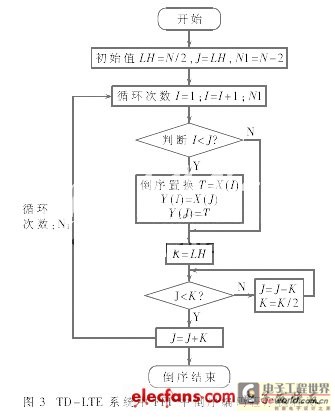
The input sequence of FFT by time extraction method is in reverse order, and the output sequence is in natural order; the input sequence of FFT by frequency extraction method is in natural order, and the output sequence is in reverse order. No matter which method is used for FFT calculation, it needs to be processed in reverse order. Reversal is an important part of the entire FFT calculation. When assembling the program, the input data is stored in the storage unit in natural order, and the natural order sequence is reversed according to the requirements of the time extraction method through the address operation.
Before reordering, the input data is stored in memory cell Y in sequence. I represents the decimal value of the sequence number of the current input data bit, and the value of I ranges from 0 to NI; J represents the decimal value of the current reverse sequence number. The first and last numbers in the input sequence do not need to be reversed, and the number of times the reverse outer loop is completed is N-2. In order to ensure the correctness of the swapped data, it is necessary to check whether I
3 Performance Analysis and Summary
In the DSP software implementation, instruction parallelism is used to optimize the program loop as much as possible, reducing or eliminating the "NOP" instructions in the program[6]. The statistical results obtained through program simulation are shown in Table 1.

As can be seen from the table, when using the TMS320C64×DSP chip, due to the ultra-high main frequency of the processor is generally 1GHz, one instruction cycle takes 1ns, and its operation rate is very fast, which can fully meet the real-time signal processing. Therefore, the implementation scheme using the rotation factor lookup table method not only simplifies the program implementation method, but also reduces the module program code writing and saves system storage space.
This paper proposes a simple and effective FFT algorithm implementation scheme, introduces the algorithm implementation method on DSP in detail, and implements it on TMS320C64x chip. The program running results show that the algorithm can meet the requirements of TD-LTE system and is feasible and efficient. This scheme has been applied in the development of LTE-TDD wireless comprehensive test instrument.
Previous article:A broadband antenna solution
Next article:Using Spread Spectrum Clocking to Reduce Electromagnetic Interference
Recommended ReadingLatest update time:2024-11-16 15:53


- High signal-to-noise ratio MEMS microphone drives artificial intelligence interaction
- Advantages of using a differential-to-single-ended RF amplifier in a transmit signal chain design
- ON Semiconductor CEO Appears at Munich Electronica Show and Launches Treo Platform
- ON Semiconductor Launches Industry-Leading Analog and Mixed-Signal Platform
- Analog Devices ADAQ7767-1 μModule DAQ Solution for Rapid Development of Precision Data Acquisition Systems Now Available at Mouser
- Domestic high-precision, high-speed ADC chips are on the rise
- Microcontrollers that combine Hi-Fi, intelligence and USB multi-channel features – ushering in a new era of digital audio
- Using capacitive PGA, Naxin Micro launches high-precision multi-channel 24/16-bit Δ-Σ ADC
- Fully Differential Amplifier Provides High Voltage, Low Noise Signals for Precision Data Acquisition Signal Chain
- Innolux's intelligent steer-by-wire solution makes cars smarter and safer
- 8051 MCU - Parity Check
- How to efficiently balance the sensitivity of tactile sensing interfaces
- What should I do if the servo motor shakes? What causes the servo motor to shake quickly?
- 【Brushless Motor】Analysis of three-phase BLDC motor and sharing of two popular development boards
- Midea Industrial Technology's subsidiaries Clou Electronics and Hekang New Energy jointly appeared at the Munich Battery Energy Storage Exhibition and Solar Energy Exhibition
- Guoxin Sichen | Application of ferroelectric memory PB85RS2MC in power battery management, with a capacity of 2M
- Analysis of common faults of frequency converter
- In a head-on competition with Qualcomm, what kind of cockpit products has Intel come up with?
- Dalian Rongke's all-vanadium liquid flow battery energy storage equipment industrialization project has entered the sprint stage before production
- Allegro MicroSystems Introduces Advanced Magnetic and Inductive Position Sensing Solutions at Electronica 2024
- Car key in the left hand, liveness detection radar in the right hand, UWB is imperative for cars!
- After a decade of rapid development, domestic CIS has entered the market
- Aegis Dagger Battery + Thor EM-i Super Hybrid, Geely New Energy has thrown out two "king bombs"
- A brief discussion on functional safety - fault, error, and failure
- In the smart car 2.0 cycle, these core industry chains are facing major opportunities!
- The United States and Japan are developing new batteries. CATL faces challenges? How should China's new energy battery industry respond?
- Murata launches high-precision 6-axis inertial sensor for automobiles
- Ford patents pre-charge alarm to help save costs and respond to emergencies
- New real-time microcontroller system from Texas Instruments enables smarter processing in automotive and industrial applications
- [Silicon Labs BG22-EK4108A Bluetooth Development Review] 1: IoT product introduction and BLE environment construction
- How does the company evaluate working from home?
- Advanced FPGA Design is a must-read for beginners of FPGA
- LM358 pin diagram, function description and working principle detailed explanation
- IIC protocol based on STM8--Example--Clock module (DS3231) reading
- A Implementation of Serial Interface Based on PCI Bus
- How to quickly design an infrared thermometer? Texas Instruments gives you tips!
- 【McQueen Trial】Blink
- EEWORLD University Hall----Design using TI's series capacitor buck converter
- Effect of Temperature on Performance and Life of Communication Switching Power Supplies

 MATLAB and FPGA implementation of wireless communication
 Digital Signal Processing (Yao Jianqing)


 京公网安备 11010802033920号