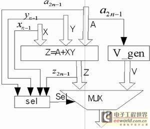
Figure 1 Saturated MAC structure diagram

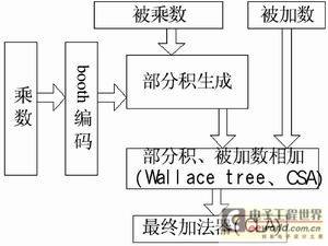
Figure 2 Optimized saturated MAC structure diagram
Introduction
In some digital signal processing applications, such as digital filtering, speech coding, and graphics processing, saturation operations are performed repeatedly. The so-called saturation operation means that when two n-bit operands are operated on, if the result overflows, the saturation value is taken. For an n-bit binary number represented by a two's complement code, the positive saturation value is 011...11, and the negative saturation value is 100...00. Saturation operations generally take two cycles, with arithmetic operations in the first cycle and saturation operations in the second cycle. More complex operations, such as MAC operations, generally perform saturation operations after completing multiplication and addition operations respectively, which usually requires more cycles. Parallel saturation operations obtain the results of serial operations within one cycle, which requires more hardware circuits to implement.
This paper designs a MAC unit to implement the operation of
=

Figure 3 Block diagram of a 24×24 high-speed multiplier-adder

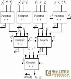
Figure 4 The largest Wallace tree structure in a parallel multiplier-accumulator

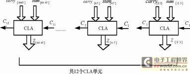
Figure 5 Implementation of the final adder
Basic structure of saturated multiplication and addition unit
In order to realize the saturation operation of
=
In order to improve the performance of the MAC unit, this paper optimizes the structure mentioned above, and the optimized structure is shown in Figure 2. The addend of the MAC unit is used as a partial product of the multiplier and participates in the partial product addition array, so that the operation of adding after completing the multiplication calculation can be omitted, shortening the delay on the critical path.
High-speed parallel multiplication and addition unit structure
This paper uses the modified booth algorithm and Wallace tree structure to implement a 24×24 high-speed parallel multiplier. Figure 3 is a block diagram of the 24×24 high-speed multiplier and adder, which is mainly composed of booth coding, partial product array, Wallace tree and final adder.
Booth coding
The multiplicand and multiplier are signed numbers represented by n-bit complement codes. In MBA (modified booth algorithm):
the number of partial products =, without loss of generality, only the case where n is an even number is discussed here.
Let: X=-an-12n-1+2i;
Y=-bn-12n-1+2i;
According to MBA, the multiplier is transformed as follows:
Y=-bn-12n-1+2i
=
Here a-1=0;
Let i=0,1,2,…(n/2-1); Then
;
;
From the above formula, it can be seen that the amount of addition calculation is reduced by half, and it can be seen that Ki+1X needs to be shifted left by two bits relative to KiX.
In MBA, the multiplier is divided into 2-bit blocks. For the jth block, the 2 bits (b2j+1, b2j) in the block and the high bit b2j-1 in the previous block are re-encoded. The encoding truth table is:
Sign extension and partial product generation
In the partial product generation process, the extension of the sign bit is generated together with the partial product. We add all the extended sign bits:
Since the sum is 48 bits, the first term in the above formula is discarded, and we get:
;
For the generation of partial products, if the multiplier Ki is negative after booth recoding, the partial product needs to be inverted and then added to 1, as shown in Table 1. Therefore, in the design, the last bit of each partial product can be added to ni, and ni=1 when the booth encoding value is negative; ni=0 when the encoding value is positive.
Adding partial products and summands
Wallace tree is an implementation structure that improves the circuit speed by increasing the parallelism of the circuit. It adds all partial products to the circuit independently and in parallel at the same time, thereby improving the operation speed. In the Wallace tree structure, we use compression units to add the partial products and summands generated during the multiplication operation. In this design, we treat the summand as a partial product and add it to the Wallace tree array, so that the operation delay of performing the addition operation after completing the multiplication operation can be omitted, thereby improving the speed of the MAC unit.
The largest tree consists of three 3-2 compression units and four 4-2 compression units. The tree has only three levels of height, which is much smaller than the height when only full adders are used, and the delay is also much smaller. For other smaller trees, it can be achieved by reducing the number of compression units. Figure 4 shows the largest Wallace tree structure in this MAC unit (where a22 is the corresponding bit of the addend). Final
adder
In the Wallace tree array, each column of the Wallace tree generates a preliminary carry term and a preliminary addition result. Finally, a fast adder must be used to add all the carry terms and addition results. In order to obtain higher performance, a carry-lookahead adder (CLA) is generally used. It can generate all the carry terms at the same time, so it can achieve extremely high speed. In the worst case, the delay is proportional to n. However, as the number of bits increases, the carry terms become more and more complex, and the area consumed accordingly becomes larger and larger, and the speed cannot be guaranteed. Research shows that the optimal number of bits for CLA is 4 bits, which can achieve the best compromise between speed and area. In this design, the addend has 48 bits in total, so it is divided into 12 blocks, each with 4 bits. The blocks are connected in series through inter-block carry. The carry of each block only affects the bits in this block and does not affect the bits of higher blocks. Figure 5 shows the implementation of the final adder.
Saturation detection and generation of saturation value
In this design, the following formula is used to detect whether the result overflows:
Where (Xn-1) is the sign of XY. In case of overflow, the saturation correction value is output through a 48-bit 2-to-1 MUX. The corrected saturation value can be calculated by the following formula:
V=
(a2n-1 is the sign bit of the addend)
Conclusion
In the implementation of the entire MAC unit, the optimized design adds the addend as part of the partial product to the Wallace tree array, thereby reducing one level of cascaded carry-lookahead adders on the critical path; the special saturation detection logic is used, so that there is no need to wait for the generation of the sum, so that the saturation detection operation can be performed in parallel with the multiplication and addition operation, and the delay of the saturation detection logic is excluded from the critical path delay. Compared with the design implementation before optimization, the speed of the MAC unit has been greatly improved. The area and delay of the optimized design implementation are concentrated on the four parts of partial product generation, Wallace tree array, final adder and 2-to-1 MUX.
Table 2 is a comparison of the area and delay before and after optimization. It can be seen from the table that both in terms of speed and area, there are great improvements after optimization.
Previous article:FPGA Implementation of GPIB Interface
Next article:Design of a high-precision digital frequency meter for synchronous period measurement based on FPGA
- High signal-to-noise ratio MEMS microphone drives artificial intelligence interaction
- Advantages of using a differential-to-single-ended RF amplifier in a transmit signal chain design
- ON Semiconductor CEO Appears at Munich Electronica Show and Launches Treo Platform
- ON Semiconductor Launches Industry-Leading Analog and Mixed-Signal Platform
- Analog Devices ADAQ7767-1 μModule DAQ Solution for Rapid Development of Precision Data Acquisition Systems Now Available at Mouser
- Domestic high-precision, high-speed ADC chips are on the rise
- Microcontrollers that combine Hi-Fi, intelligence and USB multi-channel features – ushering in a new era of digital audio
- Using capacitive PGA, Naxin Micro launches high-precision multi-channel 24/16-bit Δ-Σ ADC
- Fully Differential Amplifier Provides High Voltage, Low Noise Signals for Precision Data Acquisition Signal Chain
- Innolux's intelligent steer-by-wire solution makes cars smarter and safer
- 8051 MCU - Parity Check
- How to efficiently balance the sensitivity of tactile sensing interfaces
- What should I do if the servo motor shakes? What causes the servo motor to shake quickly?
- 【Brushless Motor】Analysis of three-phase BLDC motor and sharing of two popular development boards
- Midea Industrial Technology's subsidiaries Clou Electronics and Hekang New Energy jointly appeared at the Munich Battery Energy Storage Exhibition and Solar Energy Exhibition
- Guoxin Sichen | Application of ferroelectric memory PB85RS2MC in power battery management, with a capacity of 2M
- Analysis of common faults of frequency converter
- In a head-on competition with Qualcomm, what kind of cockpit products has Intel come up with?
- Dalian Rongke's all-vanadium liquid flow battery energy storage equipment industrialization project has entered the sprint stage before production
- Allegro MicroSystems Introduces Advanced Magnetic and Inductive Position Sensing Solutions at Electronica 2024
- Car key in the left hand, liveness detection radar in the right hand, UWB is imperative for cars!
- After a decade of rapid development, domestic CIS has entered the market
- Aegis Dagger Battery + Thor EM-i Super Hybrid, Geely New Energy has thrown out two "king bombs"
- A brief discussion on functional safety - fault, error, and failure
- In the smart car 2.0 cycle, these core industry chains are facing major opportunities!
- The United States and Japan are developing new batteries. CATL faces challenges? How should China's new energy battery industry respond?
- Murata launches high-precision 6-axis inertial sensor for automobiles
- Ford patents pre-charge alarm to help save costs and respond to emergencies
- New real-time microcontroller system from Texas Instruments enables smarter processing in automotive and industrial applications
- [Qinheng RISC-V core CH582] I2C lights up the OLED screen
- Area Occupancy Detection Reference Design for mmWave Sensors
- Multi-axis drone airbag
- I bought an old power supply, and this method of cleaning dust is the most effective
- MSP430 MCU Development Record (27)
- Comparison of three RC oscillator circuits
- ADS2021 analog circuit design, encountered problems
- [Evaluation of EC-01F-Kit, the NB-IoT development board of Anxinke] 04. Debug EC-01F with the serial port assistant and connect to Alibaba Cloud via MQTT
- Roulette Circuit
- [Fudan Micro FM33LC046N] The second PACK solves the JLINK problem but there is another problem?

 Chip Manufacturing: A Practical Tutorial on Semiconductor Process Technology (Sixth Edition)


 京公网安备 11010802033920号