Designers should be especially careful when using PWM amplifiers in noise-sensitive applications. Noise-sensitive applications include those using high-resolution encoders, ultrasonic transducers, or other low-level, medium-frequency signal generators. Grounding, shielding, and other circuit design techniques can alleviate most noise problems. The most noise-sensitive applications may require further noise reduction methods, such as PWM edge filters. Simple design guidelines can ensure effective management of capacitively coupled currents and help you gain the full benefits of PWM servo amplifiers.
PWM Scheme
PWM encodes the analog signal with a digitally compatible bi-level pulse train. There are various variations of PWM, but the most common type used in servo amplifiers is the constant carrier frequency type. Typical PWM carrier frequencies for servo amplifiers are 10 kHz to 20 kHz. The analog signal information in the PWM pulse train is encoded by the variation in pulse width. For fixed frequency PWM, designers sometimes describe the pulse width in terms of duty cycle: the ratio of the pulse width to the PWM period.
In the frequency domain, the PWM drive voltage has two main frequency components. The first is the fundamental motor drive component, which corresponds to the motor speed and the number of motor poles. This fundamental component causes the motor current that produces torque. The second frequency component is the PWM carrier frequency. Since this voltage is not related to the fundamental motor drive frequency, any current generated by the PWM component of the motor drive voltage will not have any effect on the operation of the motor. Any current at this frequency will only cause power loss in the motor. Fortunately, the PWM frequency is usually high enough that the motor inductive reactance at the PWM frequency is large. Since current is equal to voltage divided by impedance, the current at the PWM frequency is generally small.
The main reasons for using PWM motor drives are to reduce size and improve efficiency. IGBTs (insulated gate bipolar transistors) or power MOSFETs convert the DC input voltage to the motor drive voltage and are most efficient when they operate in a switching mode. The PWM signal drives the IGBT or MOSFET while rapidly switching between the fully on or fully off states. In a linear amplifier, these devices operate in their linear region, so the power loss and overall size of the driver amplifier are relatively large.
Capacitive coupling
When transistors switch between the on and off states, they pass through their linear region, dissipating energy. The faster the transistors switch, the less energy they dissipate, and the more efficient the amplifier is. If high efficiency were the only requirement for amplifier design, the design goal would be to make the transistors switch as fast as possible. However, there is usually a tradeoff. The high dv/dt caused by fast switching can couple noise into adjacent circuits. Typically, faster switching results in higher noise. Therefore, amplifier designers must strike a balance between efficiency and noise levels.
Noise is coupled through parasitic capacitance between the conductors of the motor cable and adjacent circuits (Figure 1). The figure shows a common servo motor application with a DC-powered PWM servo amplifier driving a brushless motor. The amplifier receives position feedback from an incremental encoder. In this example, both the motor cable and the encoder cable are unshielded.
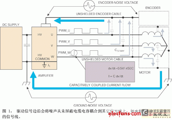
The waveforms of the amplifier PWM output voltages on phases U, V, and W are in phase, and their duty cycle is 50%. This in-phase and duty cycle condition is typical when the system is in a holding position, and the motor current and speed are close to zero. The lower half of the figure shows a detailed view of the rising edge of the phase W output. Note that this edge has a finite rise time, with a typical dv/dt of the order of 0.5V/ns. Shown below this rising edge detail is a graph of the noise currents coupled to adjacent circuits through parasitic capacitance, generated by the PWM rising edge.
The amount of parasitic capacitance between the motor conductors and adjacent conductors depends on the size, shape, orientation, and proximity of the adjacent conductors. The amount of noise current that flows is calculated using the formula I="C" dv/dt, where dv/dt is the rate of change of the PWM voltage and C is the stray capacitance value. Whether this noise current causes a functional problem in the circuit depends on the exact path it takes and the sensitivity of the adjacent circuits.
Noise currents will take the path of least impedance back to their source, the amplifier. For the frequencies generated by the PWM edges, this path is usually the path of least inductance. If a system does not have any proper shielding, the path of least impedance is difficult to define accurately. Noise currents can flow through nearby conductors, such as encoder cables and other circuits that share a common ground with the amplifier. When these currents flow through the encoder lines, a voltage is generated across the encoder and amplifier lines. If this voltage is large enough, the amplifier encoder receiver circuit can falsely detect the signal or mask true encoder transitions, thereby generating false or additional encoder counts. Similarly, these noise currents can cause voltage drops between ground-conductors, thereby causing noise on other signal lines.
When the motor control system is in the hold position, the noise current is maximum. At this time, the rising and falling edges of all three waveforms occur simultaneously. The current spikes from the PWM edges are generated at the same time and at the same point. Therefore, the net peak current capacitively coupled to the external circuit is the superposition of the individual currents of the U, V, and W phases. On the other hand, when the motor is rotating and generating torque, the PWM duty cycle of each phase is changing, and the rising and falling edges no longer coincide. At this time, the current spike frequency is higher, but the amplitude is lower.
Management of capacitively coupled currents
The problems associated with capacitively coupled PWM noise can be reduced by using cable shielding and proper grounding techniques. Grounding and shielding have two main purposes. The first is to force the capacitively coupled current to flow in a definite path; the second is to ensure that any noise voltage generated along that path does not interfere with the important signal. The motor cable shield is connected to the motor chassis and the amplifier ground, which establishes a controlled path for the capacitively coupled current to flow (Figure 2). Shielding does not eliminate capacitance, but it can control it so that the coupling effect ends at the shield and does not affect the external circuit. The ideal overall shield includes all three conductors to achieve 100% coverage and a zero impedance path for high-frequency noise currents. The zero impedance path ensures that there is no voltage drop along the shield and the entire shield is at a high voltage common potential.
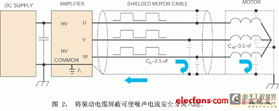
The shield connection to the motor case terminates the capacitive coupling between the motor windings and the motor case. The motor case then provides a complete shield for the motor windings. In addition, the cable shield provides a path for these currents to return to the amplifier common.
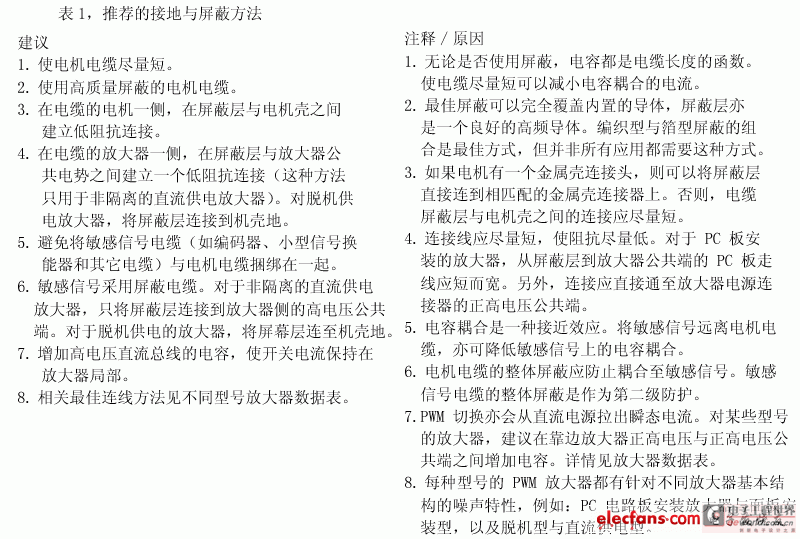
Typical values for shielded cable capacitance and motor winding to housing capacitance are on the order of 250 pF and 0.5 nF, respectively. Cable capacitance is measured for 4-conductor #16 AWG wire with aluminum foil shield. If the PWM rising edge rate is 0.5 V/ns, the peak current in the full shield is I="Cdv/dt"=(2.5 nF+0.5 nF)0.5 V/ns=1.5 A. The same calculation is used for the PWM falling edge, but the current polarity is reversed. Thus, when the motor is in the holding position, the peak current flowing in the cable shield can be expected to be up to 3 A pp. Table 1 shows the recommended grounding and shielding methods.
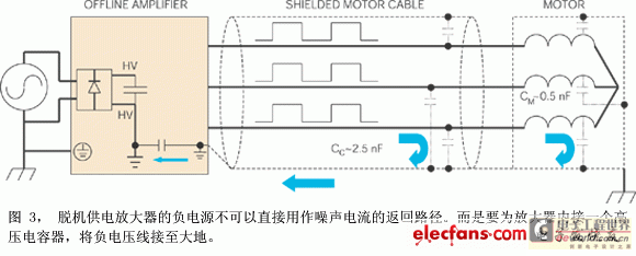
Offline powered amplifiers take their ac power from the mains and use an internal rectifier to power the dc bus (Figure 3). The negative end of the dc bus cannot be used to connect the motor cable shield because this is a non-isolated dc powered amplifier. In this topology, the bus voltage is typically 100V or much lower than earth ground potential, so connecting the cable shield to this potential would pose a safety hazard.
The operating voltage of non-isolated DC-powered amplifiers is taken from a line-isolated DC power supply. The negative voltage line of these power supplies is usually connected directly to earth ground. In this structure, it is safe, feasible and efficient to connect the cable shield to the common bus.
For offline powered amplifiers, the shield should be connected to the chassis ground of the amplifier. High voltage, safety rated capacitors built into the amplifier bypass the bus to chassis ground. This connection provides a path for noise currents to flow through the shield back to their source, the bus.
Offline-powered amplifiers generally operate at higher voltages than DC-powered amplifiers, so the dv/dt of their PWM outputs is also higher than that of DC-powered amplifiers. In addition, the cable shield is less effective than a DC-powered solution because the cable shield current flows through the internal capacitors before returning to the amplifier's bus. Therefore, PWM noise issues are more difficult to solve in systems using offline-powered amplifiers.
For noise-sensitive applications using offline-powered amplifiers, another noise-reduction tool is the PWM edge filter. A PWM edge filter uses passive components to reduce the dv/dt of the amplifier's PWM edges (Figure 4).
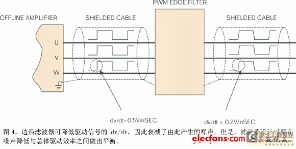
The PWM edge filter is connected in series between the amplifier and the motor to increase the rise and fall times of the PWM edges. The edge filter reduces the peak amplitude of all capacitively coupled currents. Again, there is a trade-off between the overall efficiency of the edge filter design and the effectiveness of the filter. A filter design that reduces the rise and fall times by more than an order of magnitude is too large and consumes too much power. An edge filter that reduces the rise and fall times by a moderate amount is more effective in practical applications. The example in the figure is the effect of an actual edge filter, where dv/dt is reduced from 0.5 to less than 0.2V/ns. The noise current is also reduced by the same factor: I = Cdv/dt = (2.5 nF + 0.5 nF) × 0.2V/ns = 0.6A.
To maximize the effectiveness of the edge filter, place it as close to the amplifier as possible. Shield the cable between the edge filter and the amplifier and keep it as short as possible. Maintain the shielding of the cable between the edge filter and the motor and ensure continuity between each shielded cable segment.
Previous article:Principle and structure of silicon controlled rectifier
Next article:Choosing the Right Amplifier for Strain Gage Applications
- Popular Resources
- Popular amplifiers
- High signal-to-noise ratio MEMS microphone drives artificial intelligence interaction
- Advantages of using a differential-to-single-ended RF amplifier in a transmit signal chain design
- ON Semiconductor CEO Appears at Munich Electronica Show and Launches Treo Platform
- ON Semiconductor Launches Industry-Leading Analog and Mixed-Signal Platform
- Analog Devices ADAQ7767-1 μModule DAQ Solution for Rapid Development of Precision Data Acquisition Systems Now Available at Mouser
- Domestic high-precision, high-speed ADC chips are on the rise
- Microcontrollers that combine Hi-Fi, intelligence and USB multi-channel features – ushering in a new era of digital audio
- Using capacitive PGA, Naxin Micro launches high-precision multi-channel 24/16-bit Δ-Σ ADC
- Fully Differential Amplifier Provides High Voltage, Low Noise Signals for Precision Data Acquisition Signal Chain
- Innolux's intelligent steer-by-wire solution makes cars smarter and safer
- 8051 MCU - Parity Check
- How to efficiently balance the sensitivity of tactile sensing interfaces
- What should I do if the servo motor shakes? What causes the servo motor to shake quickly?
- 【Brushless Motor】Analysis of three-phase BLDC motor and sharing of two popular development boards
- Midea Industrial Technology's subsidiaries Clou Electronics and Hekang New Energy jointly appeared at the Munich Battery Energy Storage Exhibition and Solar Energy Exhibition
- Guoxin Sichen | Application of ferroelectric memory PB85RS2MC in power battery management, with a capacity of 2M
- Analysis of common faults of frequency converter
- In a head-on competition with Qualcomm, what kind of cockpit products has Intel come up with?
- Dalian Rongke's all-vanadium liquid flow battery energy storage equipment industrialization project has entered the sprint stage before production
- Allegro MicroSystems Introduces Advanced Magnetic and Inductive Position Sensing Solutions at Electronica 2024
- Car key in the left hand, liveness detection radar in the right hand, UWB is imperative for cars!
- After a decade of rapid development, domestic CIS has entered the market
- Aegis Dagger Battery + Thor EM-i Super Hybrid, Geely New Energy has thrown out two "king bombs"
- A brief discussion on functional safety - fault, error, and failure
- In the smart car 2.0 cycle, these core industry chains are facing major opportunities!
- The United States and Japan are developing new batteries. CATL faces challenges? How should China's new energy battery industry respond?
- Murata launches high-precision 6-axis inertial sensor for automobiles
- Ford patents pre-charge alarm to help save costs and respond to emergencies
- New real-time microcontroller system from Texas Instruments enables smarter processing in automotive and industrial applications
- EEWORLD University Hall ---- Arduino Creative Collection
- My 2019 eSports Tour
- Bluetooth speaker modification
- Adafruit CLUE board
- [GD32E231 DIY Contest] Work submission: Ornamental fish tank controller
- Analysis of the setting method of single chip interrupt priority
- 【Portable Programmable Meter】Hardware is already working
- STM32H7 RAMECC function and application
- TMS320DM8168 floating-point DSP C674x POWER power supply interface and DIP switch, JTAG emulator interface
- The program encountered adb problems

 ICL7611BMTV-T


 京公网安备 11010802033920号