1 Chaos and Chaos Synchronization Principle
The so-called chaos refers to the random-like output generated by a deterministic system. The so-called deterministic circuit means that the parameters and inputs of the circuit are certain values and there are no random factors. The so-called uncertainty,
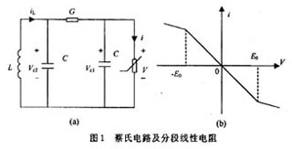
With the deepening of research on nonlinear circuits, there have been many reports of actual circuits that generate chaos and are used to study the mechanism of chaos generation. Chaos phenomena widely exist in nonlinear circuits. A typical circuit that has been studied in depth is Chua's circuit. Chua's circuit is shown in Figure 1(a). The nonlinearity in the circuit is introduced by a piecewise linear negative resistor. The volt-ampere characteristics of the nonlinear resistor are shown in Figure 1(b).

When the parameters of the circuit meet certain conditions, a self-oscillating attractor that becomes a double scroll will be generated. Figure 2 is a Chua's chaotic synchronization circuit.

2 Analog Inductor
This article introduces three commonly used analog inductor circuits: Riordan inductor circuit, lossless analog inductor circuit and low-loss analog inductor circuit.
2.1 Riordan inductor circuit
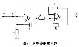
This circuit (Figure 3) is composed of 2 integrated operational amplifiers, 4 resistors and 1 capacitor. Since the operational amplifier is regarded as an ideal integrated operational amplifier, the open-loop differential mode voltage amplification factor Aod≦∞, the current flowing into the two input terminals I+≦I_≦0, U+≦U_.

The first op amp implements a non-inverting proportional arithmetic circuit, so we can get:

Therefore, the Riordan circuit can be equivalent to an analog inductor with L=R2C.
2.2 New lossless analog inductor circuit
This circuit (Figure 4) consists of 1 op amp, 4 resistors and 2 capacitors. Ui is the input signal and Uo is the output signal. From the characteristics of the ideal operational amplifier, it can be concluded that:

Therefore, this circuit can be equivalent to an analog inductor with L=2R2C.

2.3 Low-loss analog inductor circuit
This circuit (Figure 5) is composed of 1 op amp, 4 resistors and 1 capacitor. Ui is the input signal and Uo is the output signal.

According to the characteristics of the ideal operational amplifier, it can be listed:

It can be concluded that this circuit can be equivalent to a series combination of a resistor and a L=R1R2C.
3 Simulation research
Replace the inductors in Figure 2 with the above three simulated inductors for simulation. Observe the time domain waveforms, chaotic attractors and output voltage spectra of the three circuits when 18mH simulated inductors are used instead of actual inductors.
3.1 Application of Riordan circuit in chaotic synchronization circuit
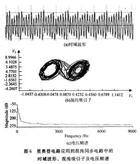
Taking the parameters in the Riordan circuit introduced earlier as R=1kΩ and the capacitor C=18nF, the Riordan circuit can be equivalent to an inductor of L=R2C=(103)2×18×10-9=18mH.
The time domain waveform, chaotic attractor and voltage spectrum obtained by applying it to the chaotic synchronous circuit are shown in Figure 6.

3.2 Application of new lossless analog inductance circuits in chaotic synchronization circuits
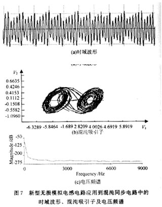
Taking the parameters in the lossless analog inductor circuit introduced earlier as R=1kΩ and C=9nF, this new analog inductor circuit can be equivalent to a L=2R2C=2×(103)2×9×10-9=18mH inductance.
The time domain waveform, chaotic attractor and voltage spectrum obtained by applying it to the chaotic synchronous circuit are shown in Figure 7.

3.3 Low-loss analog inductor circuit applied to chaotic synchronization circuit
Taking the parameters in the low-loss analog inductor circuit introduced earlier as R4=R2=0.05kΩ, R1=R3=4kΩ, and C=90nF, the low-loss analog inductor circuit can be equivalent to a L=R1R2C=4×103×0.05 ×103×90×10-9=18mH inductance.
The time domain waveform, chaotic attractor and voltage spectrum obtained by applying it to the chaotic synchronization circuit are shown in Figure 8.

4 Conclusion
By applying the Riordan circuit, the new lossless analog inductor circuit and the low-loss analog inductor circuit to the chaotic synchronous circuit for simulation research, it is found that the analog inductor can replace the actual inductor without affecting the chaotic characteristics of the chaotic circuit. Based on the analog inductor The chaotic circuit not only has the spectral characteristics of white noise, but also the autocorrelation function has a behavior close to the delta function, which provides conditions for the development and research of integrated functional chaotic oscillators. The simulation results show that the chaotic circuit based on analog inductors not only does not affect the characteristics of the chaotic circuit itself, but also has the characteristics of small size and easy integration. Therefore, it has very broad application prospects.
Previous article:555 timer trigger latch circuit composed of NAND gate
Next article:Comparison of three resistor technologies in terms of resistor power coefficient
- High signal-to-noise ratio MEMS microphone drives artificial intelligence interaction
- Advantages of using a differential-to-single-ended RF amplifier in a transmit signal chain design
- ON Semiconductor CEO Appears at Munich Electronica Show and Launches Treo Platform
- ON Semiconductor Launches Industry-Leading Analog and Mixed-Signal Platform
- Analog Devices ADAQ7767-1 μModule DAQ Solution for Rapid Development of Precision Data Acquisition Systems Now Available at Mouser
- Domestic high-precision, high-speed ADC chips are on the rise
- Microcontrollers that combine Hi-Fi, intelligence and USB multi-channel features – ushering in a new era of digital audio
- Using capacitive PGA, Naxin Micro launches high-precision multi-channel 24/16-bit Δ-Σ ADC
- Fully Differential Amplifier Provides High Voltage, Low Noise Signals for Precision Data Acquisition Signal Chain
- Innolux's intelligent steer-by-wire solution makes cars smarter and safer
- 8051 MCU - Parity Check
- How to efficiently balance the sensitivity of tactile sensing interfaces
- What should I do if the servo motor shakes? What causes the servo motor to shake quickly?
- 【Brushless Motor】Analysis of three-phase BLDC motor and sharing of two popular development boards
- Midea Industrial Technology's subsidiaries Clou Electronics and Hekang New Energy jointly appeared at the Munich Battery Energy Storage Exhibition and Solar Energy Exhibition
- Guoxin Sichen | Application of ferroelectric memory PB85RS2MC in power battery management, with a capacity of 2M
- Analysis of common faults of frequency converter
- In a head-on competition with Qualcomm, what kind of cockpit products has Intel come up with?
- Dalian Rongke's all-vanadium liquid flow battery energy storage equipment industrialization project has entered the sprint stage before production
- Allegro MicroSystems Introduces Advanced Magnetic and Inductive Position Sensing Solutions at Electronica 2024
- Car key in the left hand, liveness detection radar in the right hand, UWB is imperative for cars!
- After a decade of rapid development, domestic CIS has entered the market
- Aegis Dagger Battery + Thor EM-i Super Hybrid, Geely New Energy has thrown out two "king bombs"
- A brief discussion on functional safety - fault, error, and failure
- In the smart car 2.0 cycle, these core industry chains are facing major opportunities!
- The United States and Japan are developing new batteries. CATL faces challenges? How should China's new energy battery industry respond?
- Murata launches high-precision 6-axis inertial sensor for automobiles
- Ford patents pre-charge alarm to help save costs and respond to emergencies
- New real-time microcontroller system from Texas Instruments enables smarter processing in automotive and industrial applications
- LED Timer Keychain
- RF2051 chip
- MSP430G2 LaunchPad, how to play music with buzzer
- Allwinner V853 heterogeneous multi-core AI intelligent vision development board review - V853 YOLO V3 test
- Development board CC3200-LAUNCHXL,
- TMS320F28335 Study Notes——DMA
- RISC-V MCU Development (Part 2): Project Creation and Management
- What is this DC to AC circuit called a power supply circuit?
- MSP430 analog-to-digital conversion module--ADC12
- TPA3245 series amplifier problem

 EMC test standard: ISO 11452-4
 Three-Phase 11 kW PFC + LLC Electric Vehicle On-Board Charging (OBC) Platform User Manual (ONSEMI Semiconductor)


 京公网安备 11010802033920号