1 Hardware conversion circuit
AT89C2051 is one of the MCS51 microcontroller series. Although it has only 20 pins, it integrates the standard core of the 51 series microcontroller, including 2k program memory, 128-byte data memory, and two 16-bit timer counters. , a standard full-duplex UART and an accurate analog comparator that were not available in previous products. Figure 1 is a circuit schematic diagram of a dual-integrating A/D converter using the analog comparator of AT89C2051. Among them: the structure of the built-in analog comparator is shown in the dotted line in the figure. The positive and negative input terminals of the comparator are connected to P1.0 and P1.1 respectively. These are two open-drain outputs without pull-up resistors. and input port. When writing "1" to P1.0 and P1.1, M1 and M2 are cut off, which is equivalent to the digital part of P1.0 and P1.1 being left floating. At this time, the input of the comparator is not affected by the output of the microcontroller port. Impact; Since P1.0 and P1.1 have strong current sinking capabilities, when "0" is written, P1.0 and P1.1 can sink 20mA of current, and the saturation voltages of M1 and M2 are very low. This feature can be used to completely discharge the integrating capacitor. The output end of the comparator is connected to P3.6 inside the microcontroller, and the output result of the comparator can be obtained by reading P3.6. Therefore, using the built-in comparator of AT89C2051 and a small number of peripheral devices, a dual-integrating A/D converter can be formed. In Figure 1, I 0 is a constant current source, its current is about 0.5 ~ 2mA, C f is the integrating capacitor, the selection of C f and I 0 depends on the number of digits in A/D conversion, Vref is the reference voltage, generally Take half of the maximum analog input voltage, U2 is an analog switch, channel 0 is connected to the reference voltage, and channels 1 to 7 are connected to the analog input, that is, the A/D converter has 7 input channels.

2. Conversion process:
When the constant current source integrates the capacitor, the voltage on the integrating capacitor is linearly proportional to time. In this way, the timing counter inside the microcontroller can be used to measure the integration time of the reference voltage and the analog input voltage respectively, and then through the operation of the CPU to get the conversion result. The ports P1.2 to P1.4 of the microcontroller can be used to output the analog switch channel selection address. The timing counter T0 can be set to mode 1, 16-bit timing status, used to measure the integration time. The conversion process can be divided into 5 steps:
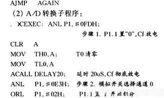
The first step is to discharge the integrating capacitor, mainly writing "0" to P1.1, using its characteristics of large sink current to discharge C f , and at the same time, the timer counter T0 is cleared.
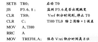
The second step is the reference voltage integration, that is, the analog switch selects channel 0, which is equivalent to connecting Vref to the positive input terminal of the comparator, writing "1" to P1.1, and starting the timer counter at the same time. In this way, I 0 begins to respond to C f Integration; the program loops to read the P3.6 status to detect the output result of the comparator. When the integrated voltage on the integrating capacitor is slightly greater than (because the comparator has extremely high gain, it can be approximately regarded as equal to) the reference voltage, compare The output of the device is inverted, and P3.6 jumps from high to low. After the program detects this jump, it stops the timer counter and saves the timer counter result T ref at this time . At this time, it can be obtained from the relationship between the constant current source and the capacitor integral: Vref = (I 0 T ref )/C f
third The first step is to discharge the integrating capacitor, that is, repeat the first step to discharge C f and clear the timer counter T0.
The fourth step is to integrate the input voltage. At this time, the analog switch can select one of channels 1 to 7, which is equivalent to connecting the analog input voltage Vx to the positive input terminal of the comparator. Repeat the second step to integrate the input voltage, and then the integral can be obtained. Time Tx, therefore, V x = (I 0 T x )/C f The integrated voltage waveform on
the integrating capacitor C f in the above 4 steps is shown in Figure 2.

The fifth step is to obtain the A/D conversion result through CPU operation. By dividing the second step result by the fourth step result, we can get:
Vref/Vx=Tref/Tx
After transformation:
Vx=(VrefTx)/Tref
The above formula is the result of A/D conversion.
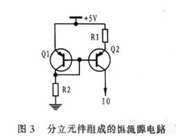
It can be seen from the above formula that the A/D conversion result Vx is only related to Vref, Tx, and Tref and has nothing to do with I 0 and C f . this point is very important. Because it means that the error caused by the temperature drift of the constant current source and the integrating capacitor is suppressed during the conversion process, thereby ensuring the stability of the A/D converter. This is also the advantage of the integral A/D converter. . Theoretically, the accuracy of the A/D converter only depends on the stability of the reference voltage and the accuracy of the microcontroller timing counter, both of which are relatively easy to guarantee. Of course, this refers to the situation when the constant current source is an ideal constant current source. In fact, the characteristics of the constant current source determine the nonlinear error of the A/D converter. Therefore, in situations with higher requirements, one with good linearity should be selected. Constant current source integrated circuits, such as LM334, etc., and when the requirements are not high, the constant current source circuit composed of discrete components as shown in Figure 3 can be used to achieve A/D conversion. At this time, the integrating capacitor can choose a polyester capacitor with a small temperature coefficient, etc.
It should be noted that since the microcontroller uses port query to detect the output result of the comparator, the port query command of the MCS51 series microcontroller needs to occupy 2 machine cycles, and the timing counter needs to add 1 to each machine cycle. Therefore, when using it, it is possible that when the output of the comparator is inverted, the program cannot stop the timer counter immediately, but has to wait until the next machine cycle runs to the CLRTR0 statement. In this way, the value of the timing counter is always an even number. If this problem is not dealt with in the program, it will cause errors. The solution is to increase the integration time of I 0 and C f , that is, double the integration time, and then divide the readings of the timing counter, Tref and Tx, by 2. In this way, the error of adding 1 more to the timing counter can be removed. Get the correct result. In other words, if you want to get 12-bit resolution, you need a 13-bit timing counter reading. Although this algorithm sacrifices the 1-bit resolution of the timing counter and lengthens the conversion cycle, it ensures the accuracy of the measurement results. For microcontrollers with analog comparator output transition interrupts, such as Z86E08, etc., the above process will be simpler. You can use a program to set the interrupt when the comparator output is inverted, and stop the timer counter at the beginning of the interrupt subroutine. The actual integration time is obtained by subtracting the number of machine cycles from the comparator interrupt to the execution of the interrupt subroutine.
Since the timing counter of AT89C2051 is 16 bits, the resolution of the A/D converter can actually reach 15 bits. Adjusting the values of I 0 and C f can change the resolution of the A/D converter. The relationship between the values of I 0 and C f and the resolution and the clock frequency of the microcontroller should satisfy the following formula:
12×2 N+1 / (f 0 V max ) ≤ C f / I O ≤ 12×2 16 / (f 0 V max )
In the formula , V max is the maximum analog input voltage, N is the number of bits of resolution, and f 0 is the clock frequency of the microcontroller. According to the above formula, the integration time should be long enough to ensure the resolution requirements during design. At the same time, it should also be ensured that the integration time cannot exceed the maximum timing value of the microcontroller to avoid overflow of the timing counter.
3 Software programming
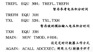
The main program of the entire working process is as follows (the program is written in MCS51 assembly language). The division subroutine and 20 μ s delay subroutine are:
(1) Initialize the main program:
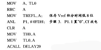
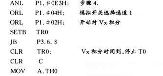
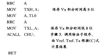
4 Conclusion
As mentioned above, a new A/D converter can be formed by using a microcontroller with an internal analog comparator, a small number of foreign components, and a little processing in the program. This method can save the cost of expanding the A/D. It occupies a large amount of I/O, and this A/D converter can achieve high resolution and accuracy, and has the characteristics of strong anti-interference ability and the resolution can be adjusted by the program, thereby increasing the application range and flexible use of the microcontroller. At the same time, the design of the application system also appears simple and ineffective.
references
1.AT89 series microcontroller. Aidil Electronics Co., Ltd.
2.Discrete Z8 Microcontrollers Databook.Zilong,Inc
Previous article:Implementation of a low-cost voltage-controlled filter
Next article:Low-power analog front-end circuit design
Recommended ReadingLatest update time:2024-11-16 17:28

- High signal-to-noise ratio MEMS microphone drives artificial intelligence interaction
- Advantages of using a differential-to-single-ended RF amplifier in a transmit signal chain design
- ON Semiconductor CEO Appears at Munich Electronica Show and Launches Treo Platform
- ON Semiconductor Launches Industry-Leading Analog and Mixed-Signal Platform
- Analog Devices ADAQ7767-1 μModule DAQ Solution for Rapid Development of Precision Data Acquisition Systems Now Available at Mouser
- Domestic high-precision, high-speed ADC chips are on the rise
- Microcontrollers that combine Hi-Fi, intelligence and USB multi-channel features – ushering in a new era of digital audio
- Using capacitive PGA, Naxin Micro launches high-precision multi-channel 24/16-bit Δ-Σ ADC
- Fully Differential Amplifier Provides High Voltage, Low Noise Signals for Precision Data Acquisition Signal Chain
- Innolux's intelligent steer-by-wire solution makes cars smarter and safer
- 8051 MCU - Parity Check
- How to efficiently balance the sensitivity of tactile sensing interfaces
- What should I do if the servo motor shakes? What causes the servo motor to shake quickly?
- 【Brushless Motor】Analysis of three-phase BLDC motor and sharing of two popular development boards
- Midea Industrial Technology's subsidiaries Clou Electronics and Hekang New Energy jointly appeared at the Munich Battery Energy Storage Exhibition and Solar Energy Exhibition
- Guoxin Sichen | Application of ferroelectric memory PB85RS2MC in power battery management, with a capacity of 2M
- Analysis of common faults of frequency converter
- In a head-on competition with Qualcomm, what kind of cockpit products has Intel come up with?
- Dalian Rongke's all-vanadium liquid flow battery energy storage equipment industrialization project has entered the sprint stage before production
- Allegro MicroSystems Introduces Advanced Magnetic and Inductive Position Sensing Solutions at Electronica 2024
- Car key in the left hand, liveness detection radar in the right hand, UWB is imperative for cars!
- After a decade of rapid development, domestic CIS has entered the market
- Aegis Dagger Battery + Thor EM-i Super Hybrid, Geely New Energy has thrown out two "king bombs"
- A brief discussion on functional safety - fault, error, and failure
- In the smart car 2.0 cycle, these core industry chains are facing major opportunities!
- The United States and Japan are developing new batteries. CATL faces challenges? How should China's new energy battery industry respond?
- Murata launches high-precision 6-axis inertial sensor for automobiles
- Ford patents pre-charge alarm to help save costs and respond to emergencies
- New real-time microcontroller system from Texas Instruments enables smarter processing in automotive and industrial applications
- USB to TTL serial port debugging tool based on 2.4G wireless transmission
- When the epidemic in Shanghai is over, I plan to develop in other cities.
- [Technical Live Broadcast] Experts from MPS, Nexperia, and Tektronix gathered to discuss the key points of new energy vehicle power design
- Dogecoin suddenly became popular. Here is a tutorial on graphics card mining
- The difference between power module ripple and noise
- The rate at which the stm32 ADC interrupt occurs is only 12k/sec
- Experiment with LIS25BA bone vibration sensor to collect audio
- 【micropython】Optimizing I2C initialization in STM32
- Power Supply Design Considerations
- Weekly review information is here~

 Intelligent computing systems (Chen Yunji, Li Ling, Li Wei, Guo Qi, Du Zidong)
 imx93-linux-kernel


 京公网安备 11010802033920号