When analyzing the transition process of a linear circuit, some singular functions are often used to describe the excitation or response in the circuit. Step function and impulse function are the two most commonly used and important functions.
1. Unit step function.
The unit step function
is defined as:
![]()
![]()
![]() (Formula 8-2-1)
(Formula 8-2-1)

Figure 8-2-1
Its waveform is shown in Figure 8-2-1. The unit step function
has a jump
at
, which is a discontinuous point. Multiplying the unit step function by a constant
gives a step function
, also known as a switching function
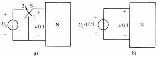
. Because it can be used to describe the switching action in the circuit, as shown in Figure 8-2-2.
The circuit shown in
Figure 8-2-2
switches the switch S from 1 to 2 at time , then
the input voltage of
the one-port network
can be expressed by a step function:
, as shown in Figure 8-2-2
.
![]()
![]()
![]()
![]()
![]()
![]()
![]()
![]()
![]()
![]()
![]()

Figure 8-2-2
The unit step function of the delay
is defined as:
![]()
![]()
![]() (Formula 8-2-2)
(Formula 8-2-2)
Its waveform is shown in Figure 8-2-3. Taking Figure 8-2-2 as an example, if
the switch S is switched from 1 to 2 at time , then
the input voltage of
the one-port network
can be expressed as a delayed step function:
.
![]()
![]()
![]()

2. Unit Impulse Function
The unit impulse function
is defined as:
![]()
 (Formula 8-2-3)
Its waveform
is shown in Figure 8-2-5. In order to better understand the unit impulse function, let's first look at the unit pulse function
. The unit impulse function
is defined as:
![]()
![]()
![]()
 (Formula 8-2-4)

Figure 8-2-5
Its waveform is shown in Figure 8-2-5
. The width of the unit pulse function is
, the height is
, and the area is 1. When the pulse width
decreases, its height
will increase, while the area remains 1. When the pulse width
tends to be infinitely small, its height
will tend to be infinitely large, but the area is still 1. When the pulse width
tends to zero, the pulse function becomes a unit impulse function.
![]()

![]()

![]()

![]()

Multiplying the unit impulse function by the constant K
gives
an impulse function with an impulse intensity of K, expressed as
.
![]()
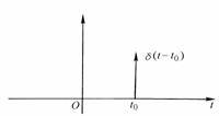
The delayed unit impulse function
is defined as:
![]()
 (Formula 8-2-5)
Its waveform is shown in Figure 8-2-6.

Figure 8-2-6
The impulse function is not a general function, but a generalized function. For its more rigorous definition, please refer to the discussion in relevant mathematics books.
Previous article:How SCSI (Small Computer System Interface) works
Next article:Loop current equation in matrix form
- Popular Resources
- Popular amplifiers
- High signal-to-noise ratio MEMS microphone drives artificial intelligence interaction
- Advantages of using a differential-to-single-ended RF amplifier in a transmit signal chain design
- ON Semiconductor CEO Appears at Munich Electronica Show and Launches Treo Platform
- ON Semiconductor Launches Industry-Leading Analog and Mixed-Signal Platform
- Analog Devices ADAQ7767-1 μModule DAQ Solution for Rapid Development of Precision Data Acquisition Systems Now Available at Mouser
- Domestic high-precision, high-speed ADC chips are on the rise
- Microcontrollers that combine Hi-Fi, intelligence and USB multi-channel features – ushering in a new era of digital audio
- Using capacitive PGA, Naxin Micro launches high-precision multi-channel 24/16-bit Δ-Σ ADC
- Fully Differential Amplifier Provides High Voltage, Low Noise Signals for Precision Data Acquisition Signal Chain
- Innolux's intelligent steer-by-wire solution makes cars smarter and safer
- 8051 MCU - Parity Check
- How to efficiently balance the sensitivity of tactile sensing interfaces
- What should I do if the servo motor shakes? What causes the servo motor to shake quickly?
- 【Brushless Motor】Analysis of three-phase BLDC motor and sharing of two popular development boards
- Midea Industrial Technology's subsidiaries Clou Electronics and Hekang New Energy jointly appeared at the Munich Battery Energy Storage Exhibition and Solar Energy Exhibition
- Guoxin Sichen | Application of ferroelectric memory PB85RS2MC in power battery management, with a capacity of 2M
- Analysis of common faults of frequency converter
- In a head-on competition with Qualcomm, what kind of cockpit products has Intel come up with?
- Dalian Rongke's all-vanadium liquid flow battery energy storage equipment industrialization project has entered the sprint stage before production
- Allegro MicroSystems Introduces Advanced Magnetic and Inductive Position Sensing Solutions at Electronica 2024
- Car key in the left hand, liveness detection radar in the right hand, UWB is imperative for cars!
- After a decade of rapid development, domestic CIS has entered the market
- Aegis Dagger Battery + Thor EM-i Super Hybrid, Geely New Energy has thrown out two "king bombs"
- A brief discussion on functional safety - fault, error, and failure
- In the smart car 2.0 cycle, these core industry chains are facing major opportunities!
- The United States and Japan are developing new batteries. CATL faces challenges? How should China's new energy battery industry respond?
- Murata launches high-precision 6-axis inertial sensor for automobiles
- Ford patents pre-charge alarm to help save costs and respond to emergencies
- New real-time microcontroller system from Texas Instruments enables smarter processing in automotive and industrial applications
- 28335 cannot connect to JTAG, urgent help!!!!!!
- Summary of pspice circuit simulation
- Playing with Zynq Serial 40——[ex59] Binocular vision image acquisition and display example based on Zynq
- Several reasons for electromagnetic flowmeter errors
- Summary and analysis of interference problems in circuit design
- Does the dummy pad have any impact on the electrical characteristics of the PCB?
- [HC32F460 Development Board Review] NO.2 Familiarity with the development process and different peripheral functions
- Classification of RFID readers and their advantages
- [Repost] Correctly select low noise amplifier
- NTC thermistor driver for MicroPython

 MAX4091AUA


 京公网安备 11010802033920号