Any circuit described by a second-order differential equation is called a second-order circuit. A second-order circuit contains two independent energy storage elements. This section takes
a series circuit as an example to discuss the zero-input response of a second-order circuit.
![]()

Figure 8-7-1
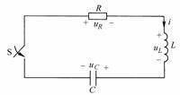
Figure 8-7-1 is
a series circuit. When
, assuming that the capacitor C
has been charged, the initial voltage is
, and the inductor L is in the zero initial state, that is
, at
the moment, the switch S
is closed. Find the zero input response
,
and
.
![]()
![]()
![]()
![]()
![]()
![]()
![]()
![]()
Select the reference direction of each voltage and current as shown in Figure 8-7-1. After the switch S is closed, write the differential equation describing the circuit according to Kirchhoff's voltage law:
![]() (Formula 8-7-1)
(Formula 8-7-1)
There are two unknown variables i
and
in (Equation 8-7-1)  .
Substituting into the above equation and eliminating it
, we get:
![]()
![]()
![]()
Right now:
![]() (Formula 8-7-2)
(Formula 8-7-2)
You can also get:
![]() (Formula 8-8-3)
(Formula 8-8-3)
(Equation 8-7-2) and (Equation 8-7-3) are completely consistent in form, both are linear constant coefficient second-order homogeneous differential equations. You can choose any one of them to solve, and now choose (Equation 8-7-2). To solve the second-order differential equation, two initial conditions are required to determine the integral constant.
According to the route switching rules:
![]() ,
,
![]()
The characteristic equation is:
![]()
The characteristic roots are:
 (Formula 8-7-4)
The characteristic roots are only related to the circuit structure and parameters.
The solutions of the equation are discussed below in three cases.
(1) When ,
that is
, , the transition process is a non-periodic case, also known as the over-damped case. In this case, the characteristic equation has two unequal negative real roots.
The general form of the general solution is:
![]()
![]()
![]()
![]() (Formula 8-7-5)
(Formula 8-7-5)
Current:
![]() (Formula 8-7-6)
(Formula 8-7-6)
The integral constant A1
is
determined by the initial conditions, and the time value of (Formula 8-7-5) (Formula 8-7-6) is taken as
:
![]()
![]()
![]() ,
,
![]()
From the initial value:
![]() ,
,
![]()
Solving the above two equations together, we get:
![]() (Formula 8-7-7)
(Formula 8-7-7)
Substitute
A1
into (Formula 8-7-5) (Formula 8-7-6) to obtain:
![]()
Capacitor voltage:
![]() (Formula 8-7-8)
(Formula 8-7-8)
Current:
![]()
Inductor voltage:
![]()
And because
, therefore:
![]()
![]() (Formula 8-7-9)
(Formula 8-7-9)
![]() (Formula 8-7-10)
(Formula 8-7-10)

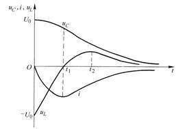
Figure 8-7-2
![]() The curves of ,
, and
time variation are shown in Figure 8-7-2. In (Formula 8-7-8),
there are two components, S1
and S2
are both negative values, and
, so
decays faster
than
. These two monotonically decreasing exponential functions determine that the discharge process of the capacitor voltage
is non-periodic.
The curves of ,
, and
time variation are shown in Figure 8-7-2. In (Formula 8-7-8),
there are two components, S1
and S2
are both negative values, and
, so
decays faster
than
. These two monotonically decreasing exponential functions determine that the discharge process of the capacitor voltage
is non-periodic.
![]()
![]()
![]()
![]()
![]()
![]()
![]()
The initial value of
the inductor voltage at is
.
At , due to
the continuous negative increase
of the current ,
it is negative;
after , the current decreases negatively and
becomes positive, and finally
decays to zero.
![]()
![]()
![]()
![]()

![]()


If
,
or
,
the analysis process is the same as above.
![]()
![]()
![]()
![]()
(2) When ,
that
is, , the transition process is critically damped, and the characteristic equation has two equal negative real roots.
![]()
![]()
![]() (Formula 8-7-11)
(Formula 8-7-11)
The general form of
capacitor voltage
is:
![]()
![]() (Formula 8-7-12)
(Formula 8-7-12)
Current:
![]() (Formula 8-7-13)
(Formula 8-7-13)
Determine the integration constants, , from the initial
conditions
:
![]()
![]()
![]() ,
,
![]()
The solution is:
![]() ,
,
![]()
therefore:
![]() (Formula 8-7-14),
(Formula 8-7-15)
(Formula 8-7-16)
(Formula 8-7-14),
(Formula 8-7-15)
(Formula 8-7-16)
![]()
![]()
![]() The curves
that change with time are similar to those shown in Figure 8-7-2
,
and the response is still non-periodic and non-oscillatory.
The curves
that change with time are similar to those shown in Figure 8-7-2
,
and the response is still non-periodic and non-oscillatory.
![]()
![]()
(3) When
,
that is
, , the transition process is underdamped and is a periodic oscillation. At this time, the characteristic equation has two conjugate complex roots with negative real parts. Let
, called the attenuation coefficient,
be the resonant angular frequency, and
be called the oscillation angular frequency, then the characteristic root is:
![]()
![]()
![]()
![]()
![]()
 (Formula 8-7-17)
The general form of
capacitor voltage
is:
![]()
![]() (Formula 8-7-18)
(Formula 8-7-18)
Current:
![]() (Formula 8-7-19)
(Formula 8-7-19)
Determine the integral constants A and from the initial values
,
and take
the values of
 (Formula 8-7-18) and (Formula 8-7-19)
at time to obtain:
![]()
![]()
![]()
Solving the equation together:
![]() ,
(Formula 8-7-20)
,
(Formula 8-7-20)
![]()
then:
![]() (Formula 8-7-21)
(Formula 8-7-21)
 (Formula 8-7-22)
 (Formula 8-7-23)

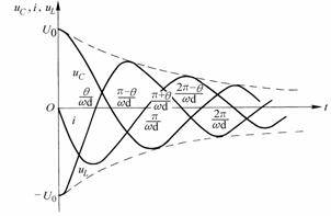
Figure 8-7-3
![]() The waveforms of ,
,
and are shown in Figure 8-7-3. They are all sinusoidal waves with exponentially decaying amplitudes. The dotted line in the figure is the envelope. When
reaches a maximum value,
it is zero; when
reaches a maximum value, I
is zero. This kind of oscillation with gradually decreasing amplitude is called damped oscillation or attenuated oscillation.
The larger the attenuation coefficient b, the faster the amplitude decays;
the smaller b, the slower the amplitude decays. The damped oscillation angular frequency
is determined by the parameters of the circuit itself.
When the resistance decreases, the attenuation coefficient
decreases, and the attenuation slows down. In
the extreme case of , the attenuation coefficient
, the response becomes an equal-amplitude oscillation, also known as an undamped oscillation. The undamped oscillation angular frequency
is equal to the resonant angular frequency
. At this time, (Formula 8-7-21) (Formula 8-7-22) (Formula 8-7-23) becomes:
The waveforms of ,
,
and are shown in Figure 8-7-3. They are all sinusoidal waves with exponentially decaying amplitudes. The dotted line in the figure is the envelope. When
reaches a maximum value,
it is zero; when
reaches a maximum value, I
is zero. This kind of oscillation with gradually decreasing amplitude is called damped oscillation or attenuated oscillation.
The larger the attenuation coefficient b, the faster the amplitude decays;
the smaller b, the slower the amplitude decays. The damped oscillation angular frequency
is determined by the parameters of the circuit itself.
When the resistance decreases, the attenuation coefficient
decreases, and the attenuation slows down. In
the extreme case of , the attenuation coefficient
, the response becomes an equal-amplitude oscillation, also known as an undamped oscillation. The undamped oscillation angular frequency
is equal to the resonant angular frequency
. At this time, (Formula 8-7-21) (Formula 8-7-22) (Formula 8-7-23) becomes:
![]()
![]()

![]()

![]()
![]()
![]()
![]()

![]() (Formula 8-7-24)
(Formula 8-7-24)
![]() (Formula 8-7-25)
(Formula 8-7-25)
![]() (Formula 8-7-26)
(Formula 8-7-26)
The above undamped oscillation is not formed by the forced action of the excitation source, and is a zero input response, so it is called free oscillation. The following is an analysis of
the long-damped periodic oscillation process of the circuit from the perspective of energy conversion.
![]()
Example 8-7-1 For the circuit shown in Figure 8-7-4, when
, switch S
is closed. Given
,
,
,
. Try to calculate
,
and ,
respectively
.
![]()
![]()
![]()
![]()
![]()
![]()
![]()
![]()
![]()

Figure 8-7-4 Example 8-7-1 Attached Figure
Solution: Figure 8-7-4 shows an RLC series circuit. Use the previous analysis results to solve it.
![]()
(1)
,
, the transition process is overdamped.
![]()
![]()

![]() ,
,
![]()
![]()
![]()
According to the route switching rules:
![]() ,
,
![]()
then:
![]()
![]()
Find:
![]() ,
,
![]()
Therefore:
![]()
(2) When
,
, the transition process is critically damped
![]()
![]()

From the initial conditions we get:
![]() ,
,
![]()
The solution is:
![]() , so:
, so:
![]()
(3) When
,
, the transition process is underdamped:
![]()
![]()

From the initial conditions we get:
![]() ,
,

The solution is:
![]()
Therefore:
![]()
Previous article:Laplace transform
Next article:Total Response of First-Order Circuits and the Three-Element Method
- Popular Resources
- Popular amplifiers
- High signal-to-noise ratio MEMS microphone drives artificial intelligence interaction
- Advantages of using a differential-to-single-ended RF amplifier in a transmit signal chain design
- ON Semiconductor CEO Appears at Munich Electronica Show and Launches Treo Platform
- ON Semiconductor Launches Industry-Leading Analog and Mixed-Signal Platform
- Analog Devices ADAQ7767-1 μModule DAQ Solution for Rapid Development of Precision Data Acquisition Systems Now Available at Mouser
- Domestic high-precision, high-speed ADC chips are on the rise
- Microcontrollers that combine Hi-Fi, intelligence and USB multi-channel features – ushering in a new era of digital audio
- Using capacitive PGA, Naxin Micro launches high-precision multi-channel 24/16-bit Δ-Σ ADC
- Fully Differential Amplifier Provides High Voltage, Low Noise Signals for Precision Data Acquisition Signal Chain
- Innolux's intelligent steer-by-wire solution makes cars smarter and safer
- 8051 MCU - Parity Check
- How to efficiently balance the sensitivity of tactile sensing interfaces
- What should I do if the servo motor shakes? What causes the servo motor to shake quickly?
- 【Brushless Motor】Analysis of three-phase BLDC motor and sharing of two popular development boards
- Midea Industrial Technology's subsidiaries Clou Electronics and Hekang New Energy jointly appeared at the Munich Battery Energy Storage Exhibition and Solar Energy Exhibition
- Guoxin Sichen | Application of ferroelectric memory PB85RS2MC in power battery management, with a capacity of 2M
- Analysis of common faults of frequency converter
- In a head-on competition with Qualcomm, what kind of cockpit products has Intel come up with?
- Dalian Rongke's all-vanadium liquid flow battery energy storage equipment industrialization project has entered the sprint stage before production
- Allegro MicroSystems Introduces Advanced Magnetic and Inductive Position Sensing Solutions at Electronica 2024
- Car key in the left hand, liveness detection radar in the right hand, UWB is imperative for cars!
- After a decade of rapid development, domestic CIS has entered the market
- Aegis Dagger Battery + Thor EM-i Super Hybrid, Geely New Energy has thrown out two "king bombs"
- A brief discussion on functional safety - fault, error, and failure
- In the smart car 2.0 cycle, these core industry chains are facing major opportunities!
- The United States and Japan are developing new batteries. CATL faces challenges? How should China's new energy battery industry respond?
- Murata launches high-precision 6-axis inertial sensor for automobiles
- Ford patents pre-charge alarm to help save costs and respond to emergencies
- New real-time microcontroller system from Texas Instruments enables smarter processing in automotive and industrial applications
- 【NUCLEO-L552ZE Review】1. Unboxing
- MicroPython Hands-on (17) - Touch pins on the control board
- Why do COG capacitors with larger package sizes have better frequency characteristics than those with smaller package sizes?
- ESP32-S2 development pitfalls (5) -- Using USB-CDC to simulate touch cursor control littlevgl
- [Gizwits Gokit3 Review] +WIFI network configuration data transmission
- 2022 New Year Matter Developer Training Sharing
- [Repost] Types and applications of ESD protection devices
- Namisoft simple program-controlled Keithly2400 multimeter (MFC)
- Solution to a Problem in DSPC6748
- Question: The number of points of the FFT algorithm of the ARM DSP library has increased to 8192?

 MSV358MU


 京公网安备 11010802033920号