The I2C bus is a simple, bidirectional two-wire synchronous serial bus.
The I2C communication protocol is widely used for communication between multiple integrated circuits (ICs) in the system due to its few pins, simple hardware implementation, strong scalability, and the fact that it does not require external transceiver devices for communication protocols such as USART and CAN. .

I2C uses two signal lines to complete information exchange, SCL is the clock signal line, and SDA is the data input/output line.
I2C can support multiple slaves (Slaver) and multiple master modes (Master). Most I2C devices support 100kHz and 400kHz modes, and some special applications can also support 3.4MHz through design.
The simple application of I2C mainly includes two aspects: I2C hardware connection and I2C communication protocol . This article briefly explains the common communication methods.
I2C hardware connection
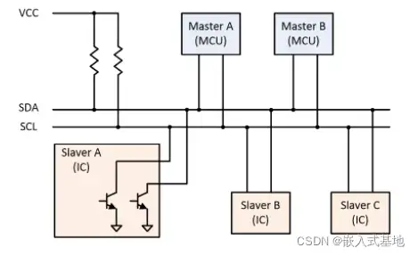
As shown in the figure below, in an I2C communication bus, multiple I2C communication devices can be connected, supporting multiple communication masters and multiple communication slaves.

SDA, SCL pins and pull-up resistors
The SDA and SCL pins of the device use OD gate outputs, and wired AND operations are performed between different devices, that is, "AND logic".
SDA and SCL require external pull-up resistors. Depending on the number of I2C devices on the bus and the communication speed of the system, different pull-up resistors should be selected in the design. The number of I2C devices determines the size of the bus capacitance on the bus. The bus capacitance and pull-up resistor limit the communication rate of the system.
Normally, the pull-up resistor for 3.3V systems is 3.3kΩ, and the pull-up resistor for 5V systems is 4.7kΩ.
When the I2C device is idle, it will output a high-impedance state. When all devices are idle and all output a high-impedance state, the pull-up resistor will pull the bus to a high level.
Multi-master and multi-slave applications
Each slave device connected to the bus has an independent address, and the host can use this address to access different devices.
When multiple hosts use the bus at the same time, in order to prevent data conflicts, arbitration can be used to determine which host device occupies the bus.
I2C communication protocol
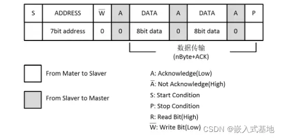
The following figure takes a master (Master) writing one byte of data to a slave (Slaver) as an example to illustrate the basic protocol of I2C communication.


Start signal (S) : When SCL is high, SDA switches from high to low.
Stop signal (P) : When SCL is high level, SDA switches from low level to high level.

Frame address: A unique 7-bit or 10-bit address for each slave device, used for address identification between master and slave devices. The I2C protocol stipulates that the device address can be 7 or 10 bits. In practice, 7-bit addresses are widely used.
Read/write bit: one bit, if the host is sending data to the slave, it is low level, and when requesting data, it is high level.
ACK/NACK: I2C data and address transmission all have responses. The response includes two signals: "ACK" and "NACK". ACK is low level and NACK is high level.
Data is valid: During data transmission, when SCL is high level, the data of SDA is valid, that is, when SDA is high level, it means data "1", when it is low level, it means data "0"; when SCL is low level, The data of SDA is invalid. Generally, at this time, the level of SDA is switched.

Previous article:Part 1 of a casual talk on microcontroller peripheral modules, illustrating what Flash, SAR, and Sigma-Delta ADCs are
Next article:You can play with microcontrollers without the actual object--Tinkercad
- Popular Resources
- Popular amplifiers
- Learn ARM development(16)
- Learn ARM development(17)
- Learn ARM development(18)
- Embedded system debugging simulation tool
- A small question that has been bothering me recently has finally been solved~~
- Learn ARM development (1)
- Learn ARM development (2)
- Learn ARM development (4)
- Learn ARM development (6)
 Professor at Beihang University, dedicated to promoting microcontrollers and embedded systems for over 20 years.
- LED chemical incompatibility test to see which chemicals LEDs can be used with
- Application of ARM9 hardware coprocessor on WinCE embedded motherboard
- What are the key points for selecting rotor flowmeter?
- LM317 high power charger circuit
- A brief analysis of Embest's application and development of embedded medical devices
- Single-phase RC protection circuit
- stm32 PVD programmable voltage monitor
- Introduction and measurement of edge trigger and level trigger of 51 single chip microcomputer
- Improved design of Linux system software shell protection technology
- What to do if the ABB robot protection device stops
- Analysis of the application of several common contact parts in high-voltage connectors of new energy vehicles
- Wiring harness durability test and contact voltage drop test method
- From probes to power supplies, Tektronix is leading the way in comprehensive innovation in power electronics testing
- From probes to power supplies, Tektronix is leading the way in comprehensive innovation in power electronics testing
- Sn-doped CuO nanostructure-based ethanol gas sensor for real-time drunk driving detection in vehicles
- Design considerations for automotive battery wiring harness
- Do you know all the various motors commonly used in automotive electronics?
- What are the functions of the Internet of Vehicles? What are the uses and benefits of the Internet of Vehicles?
- Power Inverter - A critical safety system for electric vehicles
- Analysis of the information security mechanism of AUTOSAR, the automotive embedded software framework
- [Evaluation of SGP40] + IoT remote monitoring application development - device-side development
- TPS61221 power chip management
- Showing Products (4) - Atmel Development Board
- How NFC and RFID technologies develop together
- Ultra-low power consumption and high precision ultrasonic flow meter based on MSP430
- Ultrasonic Flow Transmitter Reference Design
- What is the standard for package naming? Can you share it? Thank you!
- 2. Evaluation starts with lighting
- Slope compensation issues
- Share the OS transplantation and application of Lingdong Micro MCU based on MM32 MCU-AMetal SPI operation

 HA2-2544-7


 京公网安备 11010802033920号