
Code:
void setup(){
  pinMode(2, OUTPUT);
  pinMode(1,INPUT);}void loop(){
  if(digitalRead(1))
  {
  	  digitalWrite(2, LOW);
  }
  else
  {
  	  digitalWrite(2, HIGH);
  }
  delay(10); // Wait for 10 millisecond(s)}
button
Buttons are an input device that we use a lot, and they are an important way for microcontrollers to obtain external signals. There are also many variations of buttons in actual circuits. No matter how they change, as long as they meet the requirements of the button signals, we basically They can all be handled in the same way as pressing the keys, with little difference.
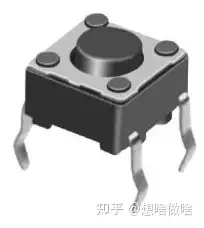
Real touch switch
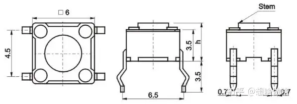
Mechanical Dimensions
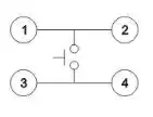
Internal circuit principle
This kind of switch is also called a tact switch. It is widely used in electronic products. It is also a switch that we often come into contact with when learning microcontrollers and embedded systems.
We usually use a switch to feel that this thing is either off or on, just these two actions, but the actual process of pressing and rebounding of the switch is like this

Ideal waveform and actual waveform
Next, let’s implement the button control LED light on and off experiment:
Experimental materials: 6*6 touch buttons, 5mm red LED light, resistor (270Ω), adjustable power supply

Experimental results: When the light touch button is pressed, the LED light turns on, and when the light touch button is released, the LED light goes out.

think? ? : Can we use MCU to accept touch button signals to control LED lights? Use a button to turn the LED light on and off. Even if you release the button, the LED light will still be on? The answer is yes, let’s do it together
The experimental schematic diagram is as follows:
The components included are: a 6*6 touch button, a 5mm red LED light, a 1/4W/270Ω in-line resistor, a 1/4W/10K in-line resistor, an arduino uno development board, and a Type USB cable. , connect some wires

Button control LED light schematic diagram
Earlier we learned how to control the LED light to turn on and off, so we won’t go into details here. Next, we learn how to detect the buttons through the microcontroller, that is, the Arduino. Before that, we first learn a little bit about the microcontroller.
High-impedance state: The Arduino pin is in a high-impedance state by default. This literal meaning is easy to understand. It means that the resistance is very large, usually at the MΩ level, so it is very unstable in this state and any interference The signal will cause false triggering, which is why I connected a pull-down resistor in the schematic diagram.
Pull-up: Connect a resistor between the microcontroller pin and the power supply, usually 10K
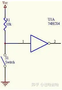
Pull-up resistor
Pulldown: Connect a resistor between the microcontroller pin and ground. Generally, 10K~47K can be selected.

Pull-down resistor
I am using the default method here, so I connected a pull-down resistor, so that when the button is not pressed, the input pin 1 of the microcontroller is low level, and when the button is pressed, it is connected to the power supply and is high level, as shown below The meaning of the code is that when pin 1 is detected to be low level, the LED light pin is set to high level, and the LED light does not light up; when pin 1 is detected to be high level, the LED light pin is set to Low level, the LED light is on.
void loop(){
  if(digitalRead(1)) //If input pin 1 is high level {
  	  digitalWrite(2, LOW); // LED light on
  }
  else // Otherwise the input pin is low {
  	  digitalWrite(2, HIGH); // LED light off }
  delay(10); // Wait for 10 millisecond(s) // Detect key presses in a 10ms period}
Experimental phenomena:

In order to see the effect more intuitively, we add two voltmeters to measure the voltage of pin 1 and pin 2 respectively, so that we can more intuitively see the voltage change effect of the LED light and button.

In the above example, we found that the LED light went out immediately after the button was released. So, can we press the button to keep the LED light on without changing the circuit, and then press it again to keep it out? Our wise ancestors have already thought of this for us. Let’s try to change the program.
code show as below:
Code principle: First detect whether the button is pressed. If pressed, delay 20ms to eliminate jitter, then detect whether it is pressed. If pressed, flip the status of the LED light, digitalWrite(2,!digitalRead( 2));, the principle of flipping is to read the current status of pin 2 and then invert it.
void setup(){
  pinMode(2, OUTPUT);
  pinMode(1,INPUT);}void loop(){
  if(1==digitalRead(1))
  {
    delay(20);
  	if(1==digitalRead(1))
    {
     	digitalWrite(2, !digitalRead(2));
    }
  }
  delay(10); // Wait for 10 millisecond(s)}
Button effect:

In the above experiment, we basically realized the status maintenance of the button control LED light. Careful friends may find that the control is very smooth. You can use your brain to further optimize the code to achieve the effect you want, such as the state machine processing method.
Summarize:
1. Buttons are a type of human-computer interaction device that we use a lot in our lives. The feel of the buttons will directly affect the experience.
2. Through the buttons, we can actually further derive the variants of the buttons. The principles are the same, but the uses are different.
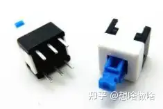
Self-locking switch

Micro Switch
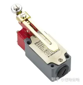
Limit switch
3. Furthermore, if the signal output by one of our circuit modules is also this high and low button level signal, it can also be treated as a button.
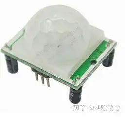
Thermal infrared sensing module

Photoelectric switch
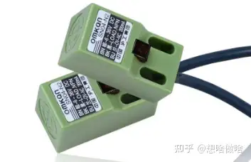
Electromagnetic induction switch
4. The same circuit with different codes can achieve different effects. This is also the fun of programming. As we accumulate basic knowledge later, we will further discover the fun of programming.
Previous article:PWM video code analysis and explanation
Next article:(2) Another way to learn basic components of LED lights
- Popular Resources
- Popular amplifiers
- Naxin Micro and Xinxian jointly launched the NS800RT series of real-time control MCUs
- How to learn embedded systems based on ARM platform
- Summary of jffs2_scan_eraseblock issues
- Application of SPCOMM Control in Serial Communication of Delphi7.0
- Using TComm component to realize serial communication in Delphi environment
- Bar chart code for embedded development practices
- Embedded Development Learning (10)
- Embedded Development Learning (8)
- Embedded Development Learning (6)
 Professor at Beihang University, dedicated to promoting microcontrollers and embedded systems for over 20 years.
- Intel promotes AI with multi-dimensional efforts in technology, application, and ecology
- ChinaJoy Qualcomm Snapdragon Theme Pavilion takes you to experience the new changes in digital entertainment in the 5G era
- Infineon's latest generation IGBT technology platform enables precise control of speed and position
- Two test methods for LED lighting life
- Don't Let Lightning Induced Surges Scare You
- Application of brushless motor controller ML4425/4426
- Easy identification of LED power supply quality
- World's first integrated photovoltaic solar system completed in Israel
- Sliding window mean filter for avr microcontroller AD conversion
- What does call mean in the detailed explanation of ABB robot programming instructions?
- CATL releases October battle report
- Battery industry in October 2024: growth momentum remains unabated!
- Mercedes-Benz will launch the eCitaro equipped with NMC4 batteries to provide high energy density and long life
- Many companies have announced progress on solid-state batteries. When will solid-state batteries go into mass production?
- Xsens Sirius Series Inertial Sensors Enable 3D Inertial Navigation in Harsh Environments
- Infineon's Automotive Landscape: From Hardware to Systems
- STMicroelectronics discloses its 2027-2028 financial model and path to achieve its 2030 goals
- 2024 China Automotive Charging and Battery Swapping Ecosystem Conference held in Taiyuan
- State-owned enterprises team up to invest in solid-state battery giant
- The evolution of electronic and electrical architecture is accelerating
- The top 10 list of big companies with the highest salaries and 996 working hours is out! Netizen: Although it’s 996, the salary is quite high~
- I saw the RISC-V Linux system
- EEWORLD University Hall ---- Computer Vision Course Tsinghua University Wang Mingzhe
- Download to get a gift! Lots of exquisite gifts are waiting for you!
-
EEWORLD University Hall----Live Replay:
takes you to learn about ADI's digital health biosensor series - Switching power supply using microcontroller for loop control
- Carrier synchronization
- Yuan Fang, what do you think of this circuit? (2)
- Popular Science Sharing - Detailed Explanation of the Working Principles of Starlink Satellites (Episode 3)
- Several key points about circuit breaker selection

 Driver Assistance Systems Brochure: Basic information, components and systems for active safety and comfort


 京公网安备 11010802033920号