1 Introduction
Embedded systems consist of embedded hardware and embedded software that is fixed in the hardware platform. In traditional small-scale embedded systems, software mostly adopts the foreground and background methods, which are usually used in simple occasions with low real-time requirements; for complex applications, the more common practice is to equip the system with an embedded real-time operating system (RTOS), which not only enables the system to have good real-time performance and reduces the workload of software compilation, but also improves the stability of the entire system. In addition, in order to simplify user programs, the system usually provides some necessary library functions for users to call. Compared with the foreground and background systems, this real-time embedded system increases the system storage space overhead. Intel 8051 series and various compatible microcontrollers are widely used in various embedded fields due to their extremely high cost performance, rich library functions and long-term technical accumulation. Due to the limitations of the addressing space of traditional microcontrollers, storage space expansion is often required in embedded applications. This paper draws on the virtual storage technology in traditional computer system design and proposes a method for expanding storage space using page grouping and virtual interface technology, taking the 8051 microcontroller as an example. This method has good compatibility with the Keil C compiler.
2. Storage system organization
2.1. Virtual Storage System
2.1. Virtual Storage System
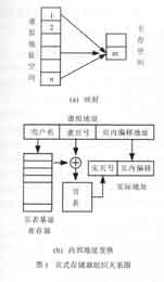
Virtual storage technology is often used in computer systems to expand the capacity of storage systems. Paged virtual memory is a commonly used organizational method. In this method, the entire virtual address space and main memory space are divided into several pages of equal capacity, and the address conversion mechanism (usually a fast address conversion table) establishes a mapping from virtual space to main memory space virtual page to real page. The organizational relationship of paged memory is shown in Figure 1.
The virtual storage system uses a set of register stacks in the computer CPU as the page table base register, as shown in Figure 1(b), which together with the page table gives the user program address. The paged virtual storage of an actual computer system is much more complicated than this, and it is also necessary to consider the external address conversion when a miss occurs and the page replacement algorithm. However, in embedded systems, these can be simplified or even omitted.

2.2. Microcontroller embedded system program storage area expansion
Inspired by the virtual memory system, we modified the above method to apply it to embedded systems. Since the external program memory capacity selected in the system design is 256k, and the addressing space of general microcontrollers (such as the 8051 series) is 64k, for simplicity, 64k is used as one page, and the 256k virtual address is divided into 4 pages and mapped to the 64k space of the microcontroller. The address conversion mechanism in the embedded system can be simplified: the microcontroller does not have a dedicated page table base address register, and different pages can be specified by additional port lines (such as P1.0, P1.1, P1.2, etc.) as the base address, and the page table query can be implemented with a jump table. However, the jump table must be correctly accessed before and after the page switch, so all 64k pages need to have an identical code segment to store common resources such as jump tables and interrupt vectors.

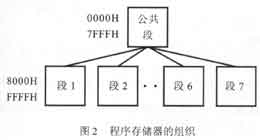
To improve memory utilization, the structure shown in Figure 2 can be used, in which the common segment stores the jump table required for mutual calls between the high 32k segments. Before each segment calls each other, it should jump to the common segment first, execute page switching, and then jump to the entry of the called program, which realizes the transformation from 18-bit virtual address to 16-bit main memory address. It is advisable to use P1.0, P1.1, and P1.2 as page base addresses to specify different pages. The corresponding jump table program structure is as follows:
ADDR: CLR EA; disable interrupt
SETB/CLR P1.0 ; switch page
SETB/CLR P1.1
SETB/CLR P1.2
SETB EA ; Enable interrupt
JMP REAL_ADDR ; Jump
The common segment (the lower 32k of the 256k memory chip) stores the operating system and other library functions provided to the user, and the other segments are used to store the user programs of the embedded system. The schematic diagram of the interface between the microcontroller and the memory using the structure of Figure 2 is shown in Figure 3. The connection method of the A0~A15 address lines is the same as the ordinary memory expansion method.

The above consideration is that the page should switch to the public code area when resetting.
Keil C51 compiler is a very popular and efficient compiler in microcontroller development applications. It supports the above-mentioned page grouping technology.
2.3. Data storage area expansion of single-chip embedded system
The introduction of an operating system into an embedded system requires a certain amount of data storage overhead. If necessary, paging technology can still be used to expand the capacity of the data storage area.
After the introduction of the operating system, there are two ways to organize the data area. The simpler method is that the operating system and the user program share a data area, and the compiler compiles the entire program together without distinguishing between system programs and user programs. However, this makes the operating system opaque to the user, and bad user programs may damage the system's data area, causing the entire system to crash.
Another corresponding method is to allocate independent data areas to the operating system and user programs, for example, 64k is allocated to the operating system and user programs respectively from the 128k data memory. Unfortunately, when the operating system and user programs are compiled together, the compiler will automatically assign different addresses to them. In this way, even if the memory is physically separated, the data area of the operating system and user programs cannot be reused, which greatly wastes the address space; and for traditional microcontrollers, the Keil C compiler only supports a maximum of 64k data area. Fortunately, this contradiction can be solved by using a virtual interface method.
To this end, the programs in the common code segment are compiled separately, and when linking and locating the target code, a fixed first address is assigned to each function of the operating system and the common library function within 0x0000~0x7FFFH. In view of the fact that the user program may call these functions, it is necessary to write a pseudo function of the same type and the same name for each of these functions. Each pseudo function contains only one transfer instruction to the real function (the entry address is known), and all these functions are stored in a header file called a virtual interface. The virtual interface file is compiled together with the user program to complete the interface between the user program and the operating system for two compilations. Obviously, this method only occupies a very small amount of code space in the user area, without wasting the user data area at all, and at the same time realizes address reuse.
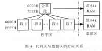
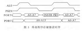
The special correspondence between the common code segment and the data area of the operating system (see Figure 4) can be easily specified through the P2 port line. From the timing of accessing the external program area of the microcontroller (Figure 5), it can be seen that after the rising edge of PSEN, instructions or instruction operands begin to appear on the data bus A0~A7. At this time, the address line A15 indicates whether the current access is the common code segment (corresponding to the high 64k of the data area) or other program segments (corresponding to the low 64k of the data area). Therefore, the address line A15 is latched at the rising edge of PSEN, and different data memory spaces can be selected with it.


3. Performance analysis of storage system
This paper implements the expansion of large-capacity memory in embedded systems based on the idea of virtual storage system. It is not difficult to see that the expansion space of the system is limited by the port line. Since one more port line is needed to construct the structure shown in Figure 2 in the same chip, the entire P1 port can be used to expand the system's program virtual space to 8M bytes for the 8051 series. The maximum capacity of the data storage area expansion is also related to the number of blocks into which the program is divided when it is compiled. The maximum capacity can reach 16M bytes, which is large enough in a single-chip embedded system.
When a program calls functions on different pages, it requires additional software switching cycles. Frequent page switching will reduce system performance. Therefore, functions should be carefully selected during compilation, and related functions should be allocated on the same page as much as possible.
Data storage area switching is implemented by hardware, and page switching does not reduce system performance. Since the operating system and user program data areas are independent of each other, the entire 64k space is available to users, which increases the transparency of the operating system.
4 Conclusion
Due to its specialization and particularity, the software and hardware design of embedded systems are different from the traditional computer system design methods. However, it is still necessary to learn from the mature design methods of traditional computer system architecture when designing embedded systems, and "tailor" them for my own use. When designing embedded platforms, the author borrowed the traditional computer virtual storage idea to expand the storage system, and applied it in actual projects, proving that this method is very effective.
Previous article:51 Single Chip Microcomputer Frequency Counter Course Design
Next article:Design of intelligent overvoltage protection module for large current converter
- Learn ARM development(16)
- Learn ARM development(17)
- Learn ARM development(18)
- Embedded system debugging simulation tool
- A small question that has been bothering me recently has finally been solved~~
- Learn ARM development (1)
- Learn ARM development (2)
- Learn ARM development (4)
- Learn ARM development (6)
 Professor at Beihang University, dedicated to promoting microcontrollers and embedded systems for over 20 years.
- LED chemical incompatibility test to see which chemicals LEDs can be used with
- Application of ARM9 hardware coprocessor on WinCE embedded motherboard
- What are the key points for selecting rotor flowmeter?
- LM317 high power charger circuit
- A brief analysis of Embest's application and development of embedded medical devices
- Single-phase RC protection circuit
- stm32 PVD programmable voltage monitor
- Introduction and measurement of edge trigger and level trigger of 51 single chip microcomputer
- Improved design of Linux system software shell protection technology
- What to do if the ABB robot protection device stops
- Wi-Fi 8 specification is on the way: 2.4/5/6GHz triple-band operation
- Wi-Fi 8 specification is on the way: 2.4/5/6GHz triple-band operation
- Vietnam's chip packaging and testing business is growing, and supply-side fragmentation is splitting the market
- Vietnam's chip packaging and testing business is growing, and supply-side fragmentation is splitting the market
- Three steps to govern hybrid multicloud environments
- Three steps to govern hybrid multicloud environments
- Microchip Accelerates Real-Time Edge AI Deployment with NVIDIA Holoscan Platform
- Microchip Accelerates Real-Time Edge AI Deployment with NVIDIA Holoscan Platform
- Melexis launches ultra-low power automotive contactless micro-power switch chip
- Melexis launches ultra-low power automotive contactless micro-power switch chip
- Signal correlation operation and algorithm analysis in single chip microcomputer program application
- 【ST NUCLEO-G071RB Review】USART
- 【TI mmWave Radar Review】Human Body Position Detection
- The electronic competition is coming again, come and vote, will you participate?
- 【FAQ】 TPS63020: Phase margin improvement method
- KiCad requires the use of the new kicad.org domain
- 【GD32307E-START】+ Dual-color OLED screen driver display
- [Automatic clock-in walking timing system based on face recognition] Maixbit K210 serial communication protocol debugging
- CAN bus receives error information? Add CRC check in the data?
- Working principle, purpose and use of flexible waveguide


 ARM Cortex M4 cookbook


 京公网安备 11010802033920号