1 Introduction
The new generation of HTU21D temperature and humidity sensor from Humirel, France, sets new standards in terms of size and intelligence: it is embedded in a dual-row flat leadless DFN package suitable for reflow soldering, with a bottom surface of 3x3mm and a height of 1.1mm. The sensor outputs a calibrated digital signal in standard I2C format.

The HTU21D temperature and humidity sensor provides an accurate and reliable temperature and humidity measurement data for OEM applications.
The interface and module of the controller are connected to achieve digital output of temperature and humidity. The resolution of HTU21D can be changed by inputting commands (8/12bit or even 12/14bit RH/T). The sensor can detect low battery state and output a checksum, which helps to improve the reliability of communication.
2. Specifications

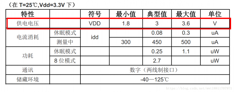
The electrical characteristics at 25 degrees Celsius and 3.3V power supply are as follows:
Printed board design notes:
If the SCL and SDA signal lines are parallel to each other and very close to each other, signal crosstalk and communication failure may occur. The solution is to place VDD or GND between the two signal lines to separate the signal lines, or use shielded cables. In addition, reducing the SCL frequency may also improve the integrity of signal transmission. A 100nF decoupling capacitor must be added between the power pins (VDD, GND) for filtering. This capacitor should be as close to the sensor as possible.
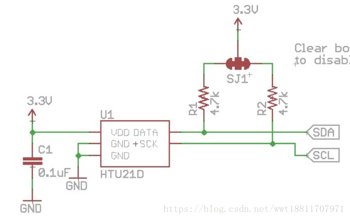
Pin definition:

This experiment uses the finished HTU21D module, which can be directly connected to the STM32 development board.
Pin Description
Power supply pins (VDD, GND) The power supply range of HTU21 is 1.8VDC - 3.6VDC, and the recommended voltage is 3.0V. A 0.1uF decoupling capacitor must be connected between the power supply (VDD) and the ground (VSS), and the capacitor should be placed as close to the sensor as possible.
Serial Clock Input (SCK) SCK is used to synchronize the communication between the microprocessor and the HTU21. Since the interface consists of completely static logic, there is no minimum SCK frequency.
Serial Data (DATA) The DATA pin is a three-state structure and is used to read sensor data. When sending commands to the sensor, DATA is valid on the rising edge of SCK and must remain stable when SCK is high. DATA changes after the falling edge of SCK. When reading data from the sensor, DATA is valid after SCK goes low and remains until the next falling edge of SCK. To avoid signal conflicts, the microprocessor should drive DATA at a low level. An external pull-up resistor (for example: 10kΩ) is required to pull the signal to a high level. The pull-up resistor is usually included in the I/O circuit of the microprocessor.
3. Communication process
Htu21d follows the standard IIC for communication. For an introduction to IIC, please see —>IIC Special Topic (I) - Basic Knowledge Preparation. This article also refers to this article —>STM32F10x_Simulating I2C to Read and Write EEPROM.
3.1 IIC start signal
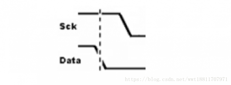
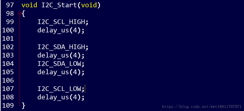
To start a transmission, sending a bit of data includes a transition of the DATA line to a low level while the SCK line is high.
3.2 IIC stop signal
To terminate the transmission and stop sending data, the DATA line jumps to a high level during the high level period of the SCK line.
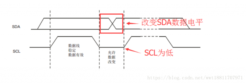
3.2 IIC data transmission
When the SCL clock level is low, the level of the SDA data line can be changed, and the SDA data is sent out during the rising edge of SCL. When SCL is high, the data on SDA remains stable.
I2C is transmitted in bytes (8 bits). After each byte is transmitted on the bus, there will be an acknowledge signal, which is always generated by the receiver. The clock of the communication process is provided by the master device (host).
IIC writes one byte:
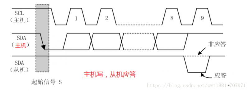

After data transmission is completed, the response operation is performed.
0: Indicates that the slave responds and can proceed to the next step;
1: Indicates that the slave does not respond and the next operation cannot be performed.
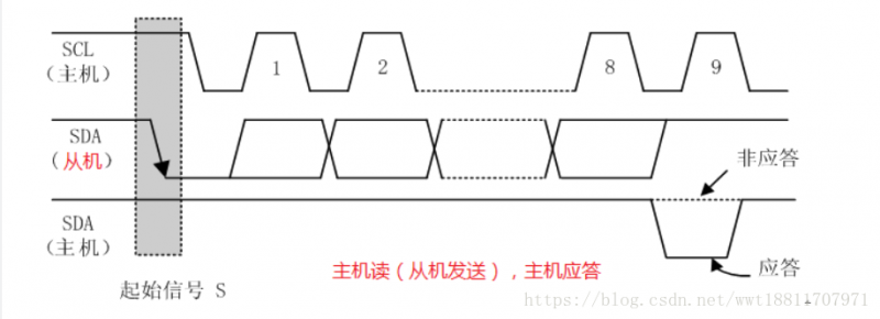
IIC reads one byte:
The IIC read operation is similar to the send operation, except that the data is transmitted in the opposite direction.

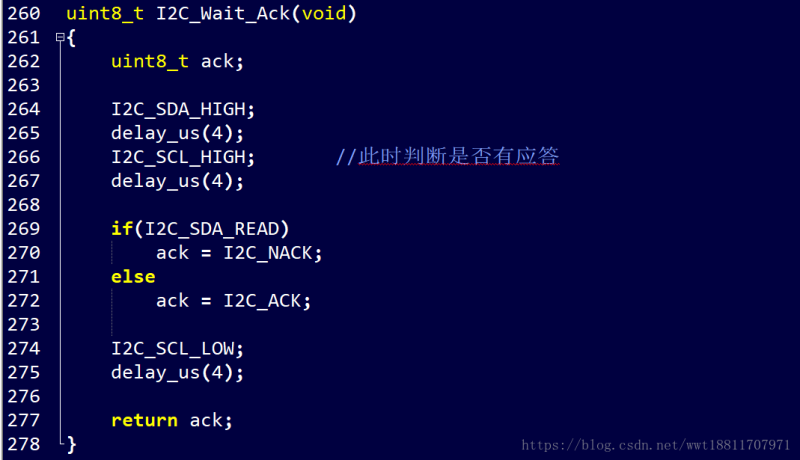
3.3 IIC response signal processing
Waiting for reply:
Generates a response:

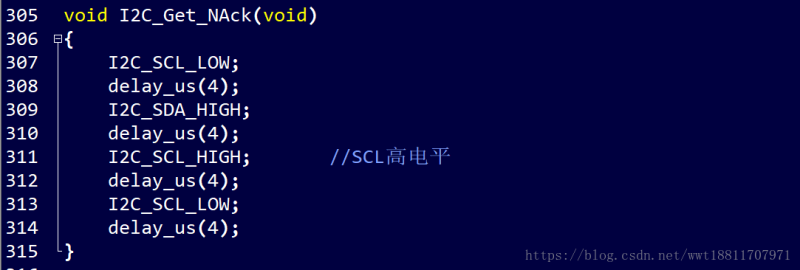
Generates a non-response:
4. HTU21D data measurement
The measurement commands are as follows:
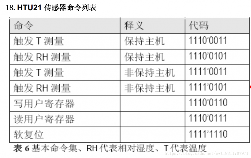
This article uses a non-hold host:
//Non-host mode
#define HTU_TEMP 0xf3
#define HTU_HUMI 0Xf5
In non-host mode, the MCU needs to query the sensor status. This process is completed by sending a start transmission timing, followed by the I2C first byte (1000'0001) as shown in the figure. If the internal processing work is completed, the microcontroller queries the confirmation signal sent by the sensor, and the relevant data can be read by the MCU. If the measurement processing work is not completed, the sensor has no confirmation bit (ACK) output, and the start transmission timing must be resent.

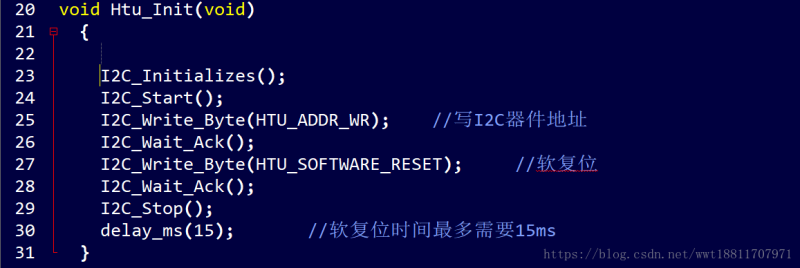
Sensor initialization:
Sensor data reading and conversion:
The default resolution of the sensor is set to 12 bits for relative humidity and 14 bits for temperature. The output data of SDA is converted into a two-byte data packet with the high byte MSB first (left-aligned). Each byte is followed by an acknowledge bit. The two status bits, i.e. the last two bits of the LSB, must be set to '0' before physical calculations are performed.
The conversion calculation is as follows:

Source code implementation:

Display method:
This experiment uses serial port printing and TFTLCD display. Serial port printing is helpful for program debugging.
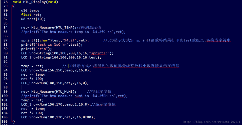
As for how to display the measured float value directly on the LCD, the code briefly introduces two methods:
LCD display mode 1: The sprintf function prints the result into the test array and converts it into a string for display (LCD_ShowString).
LCD display mode 2: Split the obtained value into integers and decimals and display them directly on the LCD (LCD_ShowxNum).
Liquid crystal displays are driven directly with reference to the atoms at the punctual point.
Previous article:STM32CubeMX learning tutorial 10: Hardware I2C reading and writing AT24C02
Next article:Summary of i2c usage of stm32f3
Recommended ReadingLatest update time:2024-11-23 08:10


- Popular Resources
- Popular amplifiers
-
 1.3-inch OLED LCD display
 -
 The STM32 MCU drives the BMP280 absolute pressure sensor program and has been debugged
 -
 STM32 MCU project example: Smart watch design based on TouchGFX (8) Associating the underlying driver with the UI
 -
 STM32 MCU project example: Smart watch design based on TouchGFX (5) Hardware driver layer programming
- Naxin Micro and Xinxian jointly launched the NS800RT series of real-time control MCUs
- How to learn embedded systems based on ARM platform
- Summary of jffs2_scan_eraseblock issues
- Application of SPCOMM Control in Serial Communication of Delphi7.0
- Using TComm component to realize serial communication in Delphi environment
- Bar chart code for embedded development practices
- Embedded Development Learning (10)
- Embedded Development Learning (8)
- Embedded Development Learning (6)
 Professor at Beihang University, dedicated to promoting microcontrollers and embedded systems for over 20 years.
- Intel promotes AI with multi-dimensional efforts in technology, application, and ecology
- ChinaJoy Qualcomm Snapdragon Theme Pavilion takes you to experience the new changes in digital entertainment in the 5G era
- Infineon's latest generation IGBT technology platform enables precise control of speed and position
- Two test methods for LED lighting life
- Don't Let Lightning Induced Surges Scare You
- Application of brushless motor controller ML4425/4426
- Easy identification of LED power supply quality
- World's first integrated photovoltaic solar system completed in Israel
- Sliding window mean filter for avr microcontroller AD conversion
- What does call mean in the detailed explanation of ABB robot programming instructions?
- STMicroelectronics discloses its 2027-2028 financial model and path to achieve its 2030 goals
- 2024 China Automotive Charging and Battery Swapping Ecosystem Conference held in Taiyuan
- State-owned enterprises team up to invest in solid-state battery giant
- The evolution of electronic and electrical architecture is accelerating
- The first! National Automotive Chip Quality Inspection Center established
- BYD releases self-developed automotive chip using 4nm process, with a running score of up to 1.15 million
- GEODNET launches GEO-PULSE, a car GPS navigation device
- Should Chinese car companies develop their own high-computing chips?
- Infineon and Siemens combine embedded automotive software platform with microcontrollers to provide the necessary functions for next-generation SDVs
- Continental launches invisible biometric sensor display to monitor passengers' vital signs
- Newbie help, about Error initializing emulator: No USB FET was found solution
- Does anyone know how to connect the windings of a 6N4P PMSM?
- [Old post ups and downs 3] Customize u8, uint8_t?
- Linux self-study notes (I) Please criticize and correct me, and learn together
- [2022 Digi-Key Innovation Design Competition] Material Unboxing Raspberry Pi 400
- How to prevent copying of FPGA code running on the board
- Characteristics that PCB should have during the design and manufacturing process
- Connectors and Connector Care
- Gallium Nitride (GaN) makes RF power amplifiers fly
- MicroRuby

 1.3-inch OLED LCD display
 The STM32 MCU drives the BMP280 absolute pressure sensor program and has been debugged
 STM32 MCU project example: Smart watch design based on TouchGFX (8) Associating the underlying driver with the UI


 京公网安备 11010802033920号