Detailed explanation of the hardware composition of the STM32 minimum system
0 composition: power reset clock debug interface start
1. Power supply: generally 3.3V LDO power supply plus multiple 0.01uf decoupling capacitors
2. Reset: There are three reset methods: power-on reset, manual reset, and program automatic reset
Usually low level reset: (51 MCU high level reset, capacitor and resistor positions swapped)
Power-on reset, at the moment of power-on, the capacitor is charged, and RESET appears a short low level. The duration of the low level is determined by the resistance and capacitance. The calculation method is as follows: t = 1.1RC (fixed calculation formula) 1.1*10K*0.0.1uF=1.1S
The required reset signal duration is about 1ms.
Manual reset: When the button is pressed, RESET and ground are connected, thus generating a low level to achieve reset.

3. Clock: crystal oscillator + starting capacitor + (feedback resistor MΩ level)
If using the internal clock:
For 100-pin or 144-pin products, OSC_IN should be grounded and OSC_OUT should be left floating.
2) For products with less than 100 pins, there are two connection methods:
i) OSC_IN and OSC_OUT are grounded through 10K resistors respectively. This method can improve EMC performance.
32.768KHZ:
You can choose to connect only a high-speed external clock of 8MHZ or an additional external low-speed clock of 32.768MHZ.
32.768KHZ clock function: used for accurate timing circuit, perpetual calendar
Usually a 32.768KHz crystal is chosen because 32768=2^15, and the frequency division setting register of the embedded chip is usually in the form of a power of 2, so after 15 times of frequency division, it is easy to get a frequency of 1HZ. Achieve precise timing. Used for precise timing circuits and perpetual calendars
Crystal oscillator: 8MHZ is generally selected for easy frequency doubling
Active: More stable, more expensive, requires power supply, no peripheral circuit required, 3-pin single-line output
Passive: basically accurate enough Convenient, flexible and cheap The biggest difference: whether it needs a separate power supply Passive crystal oscillators require external starting capacitors: There are two capacitors on both sides of the crystal oscillator

Active crystal oscillator
effect:
1. Make the equivalent capacitance at both ends of the crystal oscillator equal to or close to the load capacitance;
2. It plays a certain filtering role and removes high-frequency noise in the crystal oscillator waveform;
The size of the starting capacitor is generally selected to be 10~40pF. Of course, you can check the specific details in the user manual of different microcontrollers. If there is no specification in the manual, generally 20pF or 30pF can be selected. This is an empirical value.
Adjusting the capacitor can fine-tune the oscillation frequency:
Generally speaking, increasing the capacitance will reduce the oscillation frequency, while reducing the capacitance will increase the oscillation frequency.
Feedback resistor: 1M Negative feedback and current limiting
1. Inside the chip connected to the crystal oscillator is a linear operational amplifier, which reverses the input by 180 degrees and outputs it. The network composed of load capacitors and resistors at the crystal oscillator provides another 180 degrees of phase shift. The phase shift of the entire loop is 360 degrees, which meets the phase condition of oscillation.
2. The resistor connected to the crystal input and output is used to generate negative feedback to ensure that the amplifier operates in the high-gain linear region, generally in the M-ohm level;
3. The function of current limiting is to prevent the inverter output from overdriving the crystal oscillator and damaging the crystal oscillator. Some crystal oscillators do not need this resistor because the resistor has been integrated into the crystal oscillator.

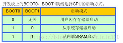
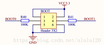
4. Startup: Users usually set Boot0 and Boot1 to 0, that is, low level.
The M3 core has 3 boot modes, and the M4 has 4. The selection is made by the BOOT0 and BOOT1 levels.

The storage media corresponding to the three startup modes of STM32 are all built-in to the chip, they are:
1) User Flash = Flash built into the chip.
2) SRAM = the RAM area built into the chip, which is the memory.
3) System memory = a specific area inside the chip. When the chip leaves the factory, a Bootloader is preset in this area, which is usually called the ISP program. The content of this area cannot be modified or erased after the chip leaves the factory, that is, it is a ROM area, which uses USART1 as the communication port.
Based on the above, M4 also adds the ability to start from the BANK1 area of FSMC.

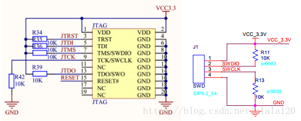
5. Debug interface: STM32 has two debug interfaces, JTAG is 5-pin, SWD is 2-wire serial (a total of four wires)

In addition, USB is used for program burning and data output: connecting to the computer USB port can also provide power for small load driving.
Usually the CH340G chip is used to realize USB to serial port conversion.
Requires a separate oscillator circuit 12MHZ
Use this chip to map the computer's USB to a serial port. Note that the serial port driver should be installed on the computer, otherwise it cannot be recognized normally.

When burning the program, we hope that BOOT0 = 1, BOOT1 = 0. After burning is completed, we hope that BOOT0 = 0, BOOT1 = 0 (in this mode, BOOT1 can be 0 or 1. Here we pull BOOT1 low, that is, BOOT1 is grounded to L during the whole process to simplify the circuit design).

Previous article:LPC824 using FlashMagic to download programs
Next article:Three methods of programming LPC2378
- Popular Resources
- Popular amplifiers
 Professor at Beihang University, dedicated to promoting microcontrollers and embedded systems for over 20 years.
- LED chemical incompatibility test to see which chemicals LEDs can be used with
- Application of ARM9 hardware coprocessor on WinCE embedded motherboard
- What are the key points for selecting rotor flowmeter?
- LM317 high power charger circuit
- A brief analysis of Embest's application and development of embedded medical devices
- Single-phase RC protection circuit
- stm32 PVD programmable voltage monitor
- Introduction and measurement of edge trigger and level trigger of 51 single chip microcomputer
- Improved design of Linux system software shell protection technology
- What to do if the ABB robot protection device stops
- Keysight Technologies Helps Samsung Electronics Successfully Validate FiRa® 2.0 Safe Distance Measurement Test Case
- Innovation is not limited to Meizhi, Welling will appear at the 2024 China Home Appliance Technology Conference
- Innovation is not limited to Meizhi, Welling will appear at the 2024 China Home Appliance Technology Conference
- Huawei's Strategic Department Director Gai Gang: The cumulative installed base of open source Euler operating system exceeds 10 million sets
- Download from the Internet--ARM Getting Started Notes
- Learn ARM development(22)
- Learn ARM development(21)
- Learn ARM development(20)
- Learn ARM development(19)
- Learn ARM development(14)
- In high-speed PCB design, these issues must be paid attention to
- Participate in the Tektronix Probe Revealing Action and Share the 2019 New Year Red Packet
- Looking for the official SDK of HiSilicon's HI3518EV300
- Temperature Measurement Record--Comparative Measurement
- TMS570x/RM4x LaunchPad: Basic setup of MIBSPI loopback mode based on examples
- [ATmega4809 Curiosity Nano Review] Serial port application preliminary: printing sine string through serial port
- MSP430 power saving mode wake-up method
- The magnetic field on the surface of a cylindrical magnet is 4000Gs. Ten of the same type of magnets stacked in the same direction have a magnetic field of only 5400GS.
- A collection of seven voltage regulator diode application circuits
- Disadvantages of Too Large Bootstrap Capacitor in DC-DC Circuits

 NE5234D/01


 京公网安备 11010802033920号