The differences between ARM, TI, ST and other companies in the eyes of embedded system learners
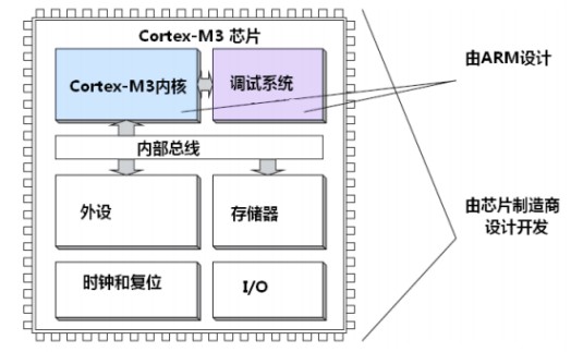
ARM is a company that makes chip standards. It is responsible for the architecture design of the chip core. Companies like TI and ST do not make standards. They are chip companies. They design their own chips based on the chip core standards provided by ARM. Therefore, any company that makes chips (such as Cortex-M3) has the same core structure. The difference lies in their memory capacity, on-chip peripherals, IO and other modules. So you will find that the number of ports, number of serial ports, and control methods of chips designed by different companies (such as Cortex-M3) are different. These resources can be designed according to their own needs. The on-chip peripherals of multiple core chips (such as Cortex-M3) designed by the same company will also be very different. Let's take a look at a picture in ARM's "Cortex-M3 Authoritative Guide":
CMSIS Standard
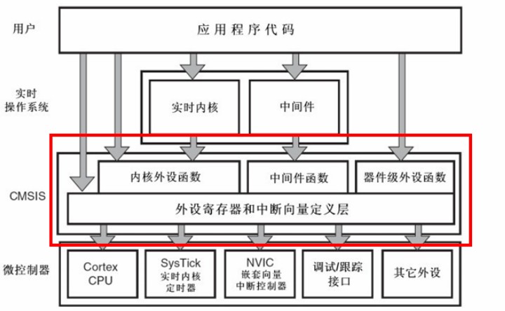
In order to make Cortex-M3 chips produced by different chip companies basically compatible in software, ARM and chip manufacturers jointly proposed a set of standard CMSIS standards (Cortex Microcontroller Software Interface Standard), which translates to "ARM Cortex™ microcontroller software interface standard". The ST official library is designed based on this set of standards. The basic structure of the CMSIS application is:
CMSIS is divided into 3 basic functional layers:
1) In-core peripheral access layer: access provided by ARM, defines the processor internal register address and function.
2) Middleware access layer: defines the general API for accessing middleware, also provided by ARM.
3) Peripheral access layer: defines the address of hardware registers and the access function of peripherals.
As can be seen from the figure, the CMSIS layer is in the middle layer of the entire system, responsible for directly dealing with the kernel and various peripherals downward, and providing a function interface called by the user program of the real-time operating system upward. If there is no CMSIS standard, then each chip company will design the library function in its own style, and the CMSIS standard is to force the chip production company to design the library function according to the CMSIS specification.
A simple example
When we use the STM32 chip, we must first initialize the system. The CMSIS specification stipulates that the name of the system initialization function must be SystemInit, so each chip
company must use SystemInit to initialize the system when writing its own library function. CMSIS also has a series of regulations on the standardization of the file names of various peripheral driver files, as well as the standardization of function names. The function name GPIO_ResetBits mentioned in the previous section cannot be defined casually, and must follow the CMSIS specification. As for the specific content of CMSIS, there is no need to say more. Friends who need to know more can search for information online.
The structure of the STM32 official firmware library package
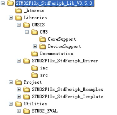
The directory structure of the official V3.5 version of the firmware library package:
Libraries folder
There are two directories, CMSIS and STM32F10x_StdPeriph_Driver, which contain all subfolders and files of the firmware library core. The CMSIS directory contains the startup files, and STM32F10x_StdPeriph_Driver contains the STM32 firmware library source code files. The inc directory under the source file directory contains the stm32f10x_xxx.h header file, which does not need to be modified. The src directory contains the firmware library source code files in the format of stm32f10x_xxx.c. Each .c file corresponds to a corresponding .h file. The files here are also the core files of the firmware library, a set of files corresponding to each peripheral.
Project folder
There are two folders. As the name implies, the STM32F10x_StdPeriph_Examples folder contains the source code of the firmware examples provided by ST. In the future development process, you can refer to and modify the official examples to quickly drive your own peripherals. Many examples of development boards refer to the official routine source code, which is very important for future learning. The STM32F10x_StdPeriph_Template folder contains the project template. The Utilities file contains some corresponding source codes of the official evaluation board.
Firmware library help documentation
There is also a stm32f10x_stdperiph_lib_um.chm file in the root directory. You can open it directly to find out that this document is very useful in the learning process.
Key Documents
Provide access to the M3 kernel interface file
The core_cm3.c and core_cm3.h files are located in the \Libraries\CMSIS\CM3\CoreSupport directory. They are provided by ARM and are the same for all CM3 core chips. You never need to modify this file!
Startup files and files with relatively basic register definitions and interrupt vector definitions
There are three files in the \Libraries\CMSIS\CM3\DeviceSupport directory: system_stm32f10x.c, system_stm32f10x.h and stm32f10x.h files.
system_stm32f10x.c, system_stm32f10x.h files
There is a very important SystemInit() function in this pair of files. This function will be called when our system starts up to set the entire clock system of the system.
stm32f10x.h file
This file is very important. As long as you do STM32 development, you will almost always have to check the definitions related to this file. When you open this file, you can see that there are many structures and macro definitions. This file mainly contains system register definition declarations and package memory operations...
Startup File
Located in the folder DeviceSupport\ST\STM32F10x\startup, in the directory \startup\arm, we can see 8 .s files starting with startup. The reason why there are 8 startup files here is that the startup files for chips of different capacities are different. For the 103 series, 3 of the startup files are mainly used:
startup_stm32f10x_ld.s: Applicable to small-capacity products
startup_stm32f10x_md.s: Applicable to medium-capacity products
startup_stm32f10x_hd.s: Applicable to large-capacity products
The capacity here refers to the size of FLASH. The judgment method is as follows:
Small capacity: FLASH ≤ 32K
Medium capacity: 64K ≤ FLASH ≤
128K Large capacity: 256K ≤ FLASH
The STM32-F103-ZET06 I use is a large-capacity product, so when doing the project, I choose the startup_stm32f10x_hd.s file
Function of startup file: Open the startup file and have a look: The startup file is mainly used to initialize the stack, interrupt vector table and interrupt function definition. The startup file should lead to the main function. The Reset_Handler interrupt function is the only interrupt handling function implemented, and other interrupt functions are basically dead loops. Tracing the project, you will find that Reset_handler will be called when
our system starts. Let's take a look at the Reset_handler code:
; Reset handler
Reset_Handler PROC
EXPORT Reset_Handler [WEAK]
IMPORT __main
IMPORT SystemInit
LDR R0, =SystemInit
BLX R0
LDR R0, =__main
BX R0
ENDP
According to IMPORT __main, the main function is imported here, and before entering the main function, the SystemInit system initialization function is called. Note: The boot program enters __main (this __main is a function in C_Library, not main()). The startup file here only talks about this: For details, you can search for the analysis of the startup file of the corresponding chip model
Several other files stm32f10x_it.c, stm32f10x_it.h and stm32f10x_conf.h files
As the name implies, stm32f10x_it.c and stm32f10x_it.h are used for interrupt service functions. When you open the stm32f10x_conf.h (confer: see) file, you can see a bunch of #include. When you build a project, you can comment out some peripheral header files that you don't use.
Previous article:STM32 firmware library file tree and detailed structure
Next article:Understanding of the programming structure of STM32 firmware library files
Recommended ReadingLatest update time:2024-11-16 13:07


- Popular Resources
- Popular amplifiers
 Professor at Beihang University, dedicated to promoting microcontrollers and embedded systems for over 20 years.
- Innolux's intelligent steer-by-wire solution makes cars smarter and safer
- 8051 MCU - Parity Check
- How to efficiently balance the sensitivity of tactile sensing interfaces
- What should I do if the servo motor shakes? What causes the servo motor to shake quickly?
- 【Brushless Motor】Analysis of three-phase BLDC motor and sharing of two popular development boards
- Midea Industrial Technology's subsidiaries Clou Electronics and Hekang New Energy jointly appeared at the Munich Battery Energy Storage Exhibition and Solar Energy Exhibition
- Guoxin Sichen | Application of ferroelectric memory PB85RS2MC in power battery management, with a capacity of 2M
- Analysis of common faults of frequency converter
- In a head-on competition with Qualcomm, what kind of cockpit products has Intel come up with?
- Dalian Rongke's all-vanadium liquid flow battery energy storage equipment industrialization project has entered the sprint stage before production
- Allegro MicroSystems Introduces Advanced Magnetic and Inductive Position Sensing Solutions at Electronica 2024
- Car key in the left hand, liveness detection radar in the right hand, UWB is imperative for cars!
- After a decade of rapid development, domestic CIS has entered the market
- Aegis Dagger Battery + Thor EM-i Super Hybrid, Geely New Energy has thrown out two "king bombs"
- A brief discussion on functional safety - fault, error, and failure
- In the smart car 2.0 cycle, these core industry chains are facing major opportunities!
- The United States and Japan are developing new batteries. CATL faces challenges? How should China's new energy battery industry respond?
- Murata launches high-precision 6-axis inertial sensor for automobiles
- Ford patents pre-charge alarm to help save costs and respond to emergencies
- New real-time microcontroller system from Texas Instruments enables smarter processing in automotive and industrial applications
- [GD32L233C-START Review] - VII. SPI mode driving 1.5-inch OLED screen
- My creative plan and functional implementation plan
- The more I read, the more I like these sentences. Each sentence is more philosophical than the last, and each sentence is very inspiring.
- 【Want to buy】College students want to buy ATmega16 development board
- AC-DC controllers, gate drivers, digital isolators
- kernel make zImage compilation failed
- 2019 Tektronix OPEN-DAY opens: Hold your DUT and test thoroughly
- The relationship between FPGA memories
- Show off the Sony headphones I got from EEWORLD
- Single tube amplifier


 usb_host_device_code
 Transplantation of real-time operating system RT-ThreadSmart on STM32MP1


 京公网安备 11010802033920号