The serial port control register of the microcontroller is SCON, and its format is as follows:
The serial port has four working modes, namely 00, 01, 10, and 11. Mode 0 is a synchronous shift register, and modes 1, 2, and 3 are asynchronous 10, 11, and 11-bit transceiver modes. Mode 1, i.e. 10-bit asynchronous transceiver mode, is commonly used.
The specific analysis of the 10-bit data transmission and reception of mode 01 is as follows:


As above, when the microcontroller needs to receive data, it also executes the same steps. First, it receives 8 bits of data, and then sets the receiving flag RI to 1.
The initialization steps of the serial port are mainly to set the timer 1 that generates the baud rate, the serial port control box interrupt control, the steps are as follows:
Code:
//Serial port initialization program
TMOD&=0x0f;
TMOD|=0x20;
TH1=0XFD; //Set the baud rate to 9600
TL1=0xFD;
TR1=1; //Start timer T1
SCON=0X50; //10-bit data is sent and received asynchronously, the baud rate is controlled by timer T1, allowing serial port reception
ES=1; //Enable serial port interrupt
//Serial port initialization completed
Below I wrote a program for serial port communication with PC:
#include
unsigned char flag,i;
unsigned int k,j;
unsigned char a[32]={0};
unsigned char code table[6]="I get ";
void init()
{
TMOD=0x20; //Set timer working mode 2
TH1=0xfd; //Load initial value into timer 1
TL1=0xfd; //same as above
TR1=1; //Start T1 timer
SM0=0; //Set working mode 1
SM1=1; //same as above
REN=1; // Allow serial port to receive
EA=1; //Open the general interrupt
ES=1; //Open serial port interrupt
}
void main()
{
init();
while(1)
{
if(flag==1)
{
ES=0;
for(i=0;i<6;i++)
{
SBUF=table[i];
while(!TI);
TI=0;
}
ES=1;
for(k=0;k<0xFFFF;k++);
for(i=0;i<32;i++)
{
SBUF=a[i];
while(!TI);
TI=0;
}
flag=0;
}
}
}
void ser() interrupt 4 //interrupt program, receive data block, flag position 1
{
flag=1;
if(RI==1){
a[j++]=SBUF;
RI=0; //Manual clear
}
}
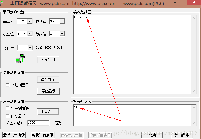
The serial communication effect is as follows:
But there is a small problem with my program. I have tried many ways to solve it, but all failed. When the data I input is greater than 2 bytes, it can only return the first two bytes of data. As shown below:
Previous article:Interaction with host computer via serial communication of C51 MCU
Next article:A Brief Discussion on UART Serial Communication (Part 3) -- Character and Data Conversion
- Popular Resources
- Popular amplifiers
- Naxin Micro and Xinxian jointly launched the NS800RT series of real-time control MCUs
- How to learn embedded systems based on ARM platform
- Summary of jffs2_scan_eraseblock issues
- Application of SPCOMM Control in Serial Communication of Delphi7.0
- Using TComm component to realize serial communication in Delphi environment
- Bar chart code for embedded development practices
- Embedded Development Learning (10)
- Embedded Development Learning (8)
- Embedded Development Learning (6)
 Professor at Beihang University, dedicated to promoting microcontrollers and embedded systems for over 20 years.
- Intel promotes AI with multi-dimensional efforts in technology, application, and ecology
- ChinaJoy Qualcomm Snapdragon Theme Pavilion takes you to experience the new changes in digital entertainment in the 5G era
- Infineon's latest generation IGBT technology platform enables precise control of speed and position
- Two test methods for LED lighting life
- Don't Let Lightning Induced Surges Scare You
- Application of brushless motor controller ML4425/4426
- Easy identification of LED power supply quality
- World's first integrated photovoltaic solar system completed in Israel
- Sliding window mean filter for avr microcontroller AD conversion
- What does call mean in the detailed explanation of ABB robot programming instructions?
- STMicroelectronics discloses its 2027-2028 financial model and path to achieve its 2030 goals
- 2024 China Automotive Charging and Battery Swapping Ecosystem Conference held in Taiyuan
- State-owned enterprises team up to invest in solid-state battery giant
- The evolution of electronic and electrical architecture is accelerating
- The first! National Automotive Chip Quality Inspection Center established
- BYD releases self-developed automotive chip using 4nm process, with a running score of up to 1.15 million
- GEODNET launches GEO-PULSE, a car GPS navigation device
- Should Chinese car companies develop their own high-computing chips?
- Infineon and Siemens combine embedded automotive software platform with microcontrollers to provide the necessary functions for next-generation SDVs
- Continental launches invisible biometric sensor display to monitor passengers' vital signs
- [Repost] What are the key points to follow in EMC processing?
- 20 "Million Miles" Raspberry Pi Car - Motor Control Learning (Control Speed)
- [RVB2601 debug record] The function in the c file is not declared in the header file
- [Raspberry Pi Pico Review] On-chip temperature detection
- STM32F407 simple vision board (recognition of QR codes, data matrix codes, apriltags, round and square shape detection)
- A Brief Review of EDA Software at Home and Abroad
- 【ST NUCLEO-G071RB Review】PWR
- There are many tricks for salary cuts and layoffs. What should you do if you encounter such a situation?
- Have you ever seen Koizumi suffer so badly? - The Chinese people are so happy
- [AB32VG1 development board review] TF card and file reading and writing applications


 HFA9P0003-9-T


 京公网安备 11010802033920号