I have been working on a stm32 project recently and have been struggling with its startup method.
I saw a good article and reposted it. The format of the original article is not very good, and there are many strange things in the content (especially the second article, I just think the original article is original, but I don’t understand the author’s ideas), and I deleted and modified them one by one. Friends who want to read the original article, the link is as follows:
http://www.ithao123.cn/content-3065243.html Duanxx’s STM32 learning: Boot mode, BOOT0 and BOOT1 detailed explanation
http://bluefish.blog.51cto.com/214870/1239098 The role of pull-up resistors and pull-down resistors
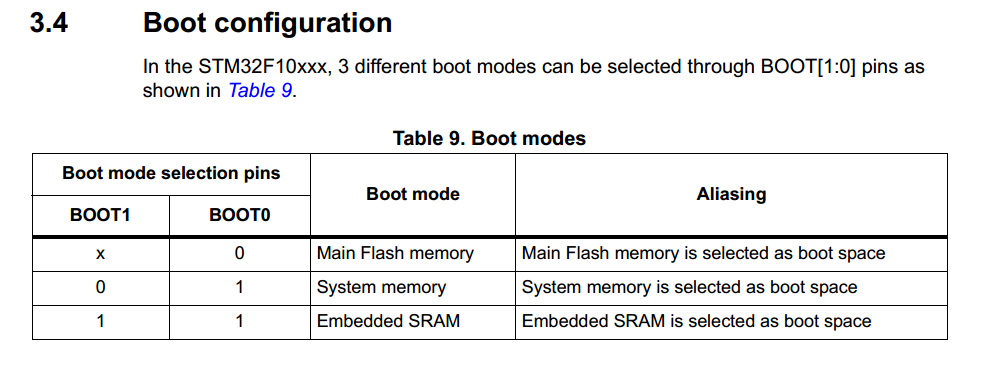
The so-called boot, generally speaking, means that after we download the program and restart the chip, the value of the BOOT pin will be latched at the fourth rising edge of SYSCLK. Users can select the boot mode after reset by setting the state of the BOOT1 and BOOT0 pins.
Main Flash memory is the built-in Flash of STM32. Generally, when we download programs using JTAG or SWD mode, they are downloaded to this memory. After restarting, the program is started directly from this memory.
System memory is started from system memory. The program function started in this mode is set by the manufacturer. Generally speaking, this startup mode is rarely used. System memory is a specific area inside the chip. When STM32 leaves the factory, ST presets a BootLoader in this area, which is what we often call the ISP program. This is a ROM and cannot be modified after leaving the factory.
Generally speaking, when we choose this startup mode, it is to download the program from the serial port, because the firmware of the serial port download program is provided in the BootLoader provided by the manufacturer, and the program can be downloaded to the system's Flash through this BootLoader. However, this download method requires the following steps:
Step 1: Set BOOT0 to 1, BOOT1 to 0, and then press the reset button to start the BootLoader from the system memory.
Step 2: Finally, with the help of BootLoader, download the program to Flash through the serial port
Step 3: After the program is downloaded, it is necessary to set BOOT0 to GND and reset it manually. In this way, STM32 can be started from Flash.
It can be seen that it is quite troublesome to download the program via the serial port. It requires jumping back and forth, and does not pay much attention to the user experience.
Embedded SRAM has built-in SRAM. Since it is SRAM, it naturally has no program storage capability. This mode is generally used for program debugging.
If I only modify a small part of the code, then I need to erase the entire Flash again, which is time-consuming. I can consider starting the code from this mode (that is, in the memory of STM32) for fast program debugging. After the program debugging is completed, download the program to SRAM.
Therefore, the more common choice is to ground BOOT0. Of course, if you draw the stm32 system board yourself, it is best to keep the other two boot methods. It is still necessary to use SRAM for debugging large programs.
Let's talk about the difference between pull-up resistors and pull-down resistors:
pull-up resistors clamp uncertain signals at a high level through a resistor, and this resistor also plays a role in current limiting. Similarly, pull-down resistors clamp uncertain signals at a low level. Pull-up resistors refer to the input current of the device, while pull-down refers to the output current.
So when do you use pull-up and pull-down resistors?
1. When a TTL circuit drives a CMOS circuit, if the high level output by the TTL circuit is lower than the lowest high level of the CMOS circuit (generally 3.5V), then it is necessary to connect a pull-up resistor to the output of the TTL to increase the value of the output high level.
2. OC gate circuits must be added with pull-up resistors to increase the output high level value.
3. In order to increase the driving ability of the output pins, some microcontroller pins often use pull-up resistors.
4. On CMOS chips, in order to prevent damage caused by static electricity, unused pins cannot be left floating. Generally, pull-up resistors are connected to reduce input impedance and provide a discharge path.
5. Pull-up resistors are added to the pins of the chip to increase the output level, thereby increasing the noise tolerance of the chip input signal and enhancing anti-interference ability.
6. Improve the anti-electromagnetic interference capability of the bus. When the pin is left floating, it is more susceptible to external electromagnetic interference.
7. Resistance mismatch in long-line transmission can easily cause reflected wave interference. Pull-down resistors are resistor matching, which effectively suppresses reflected wave interference.
In addition, the principles for selecting the resistance value of the pull-up resistor include:
1. It should be large enough to save power and the current injection capacity of the chip; the larger the resistance, the smaller the current.
2. It should be small enough to ensure sufficient drive current; the smaller the resistance, the larger the current.
3. For high-speed circuits, a pull-up resistor that is too large may flatten the edge.
Taking the above three points into consideration, it is usually selected between 1k and 10k. The same is true for the pull-down resistor.
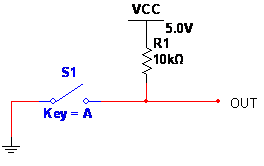
Regarding the pull-up resistor, see the picture.
As input, VCC equals 1, and GND = 0. 
If the key is short-circuited (pressed), the resistance is zero, the key is pressed, Out = 0, when the key is disconnected, Out =? Obviously, when Out is floating, VCC is output, which can be measured with an instrument. This VCC is generated by R1 "pull-up". As the name suggests, R1 is the pull-up resistor. The size of the pull-up resistor depends on the need to connect the output to the load. Usually, the logic circuit has a large impedance for high-level output and requires a small output current. The voltage drop on the pull-up resistor can be ignored. Of course, the pull-up resistor cannot be too large, otherwise it cannot be ignored.
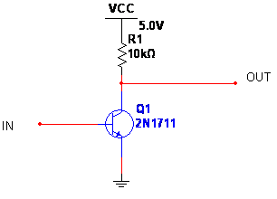
The actual circuit also has this structure 
, where R1 is also a pull-up resistor.
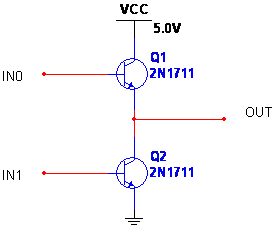
The output structure of the microcontroller P0 port is similar to the following figure. In fact, a field effect tube may be used. 
When Q1 and Q2 are turned on, they can output 0 and 1. What if Q1 and Q2 are not turned on? If you want to output 1, what should you do? Connect an external pull-up resistor!
Why use a pull-up resistor:
Generally, when used for single-key triggering, if the IC itself does not have an internal resistor, in order to keep the single key in an untriggered state or return to the original state after being triggered, a resistor must be connected outside the IC.
Regarding pull-down resistors, they are rarely used. The principle is the same as above, except that they are "pulled down" to GND through resistors.
No further details are given here
Digital circuits have three states: high level, low level, and high impedance state. In some applications, high impedance state is not desired. Pull-up resistors or pull-down resistors can be used to stabilize the circuit, depending on the design requirements! Generally speaking, I/O ports can be set, some cannot be set, some are built-in, and some need to be external. The output of the I/O port is similar to the C of a transistor. When C is connected to the power supply through a resistor, the resistor becomes a pull-up resistor. In other words, if the port is normally at a high level, when C is connected to the ground through a resistor, the resistor is called a pull-down resistor, making the port usually at a low level.
Pull-up resistors are used to provide current when the bus driving capability is insufficient. Generally speaking, it is to pull current, and pull-down resistors are used to absorb current, that is, to sink current.
Previous article:The importance of parallel capacitors at the power supply end of STM32 microcontroller
Next article:STM32 controls 3 ultrasonic sensors
- Popular Resources
- Popular amplifiers
 Professor at Beihang University, dedicated to promoting microcontrollers and embedded systems for over 20 years.
- LED chemical incompatibility test to see which chemicals LEDs can be used with
- Application of ARM9 hardware coprocessor on WinCE embedded motherboard
- What are the key points for selecting rotor flowmeter?
- LM317 high power charger circuit
- A brief analysis of Embest's application and development of embedded medical devices
- Single-phase RC protection circuit
- stm32 PVD programmable voltage monitor
- Introduction and measurement of edge trigger and level trigger of 51 single chip microcomputer
- Improved design of Linux system software shell protection technology
- What to do if the ABB robot protection device stops
- Huawei's Strategic Department Director Gai Gang: The cumulative installed base of open source Euler operating system exceeds 10 million sets
- Download from the Internet--ARM Getting Started Notes
- Learn ARM development(22)
- Learn ARM development(21)
- Learn ARM development(20)
- Learn ARM development(19)
- Learn ARM development(14)
- Learn ARM development(15)
- Analysis of the application of several common contact parts in high-voltage connectors of new energy vehicles
- Wiring harness durability test and contact voltage drop test method
- ADAFRUIT PYBADGE LC CAN RUNNING MAKECODE ARCADE, CIRCUITPYTHON AND ARDUINO
- STSPIN32F0 FOC control board drives DJI model aircraft motor/single resistor/schematic diagram/code/debugging instructions and other information are open source
- EEWORLD University Hall----Live Replay: The new Infineon MOSFET based on Source-down technology effectively improves power density, which is visible to the naked eye
- Keil registration machine 2032
- March 19 live broadcast review: Introduction to ST MEMS sensor development kit (including video, presentation documents, Q&A summary)
- Recruiting AE (Application Engineer) Manager - Motor Drive Direction 20-25K/month*14
- Help Arteli grow, tell us your story with Arteli
- How do I use TINA-TI to simulate a circuit that may contain non-TI components?
- About the problem of changing micro usb to TYPE-C
- What do you most expect humanoid robots of the future to do: replace humans, serve humans, or surpass humans?


 NCX2220GM,125


 京公网安备 11010802033920号