1.1 Introduction
With the development of computer technology and power electronics technology, variable frequency drive technology is increasingly used in the field of AC speed regulation due to its excellent performance.
The main drive waveforms used in variable frequency drive are SPWM and SVPWM. SPWM is simple in principle and easy to implement, and is currently the most widely used variable frequency drive waveform. However, it has a fatal weakness: its power utilization rate is not high (only 86%) and the harmonic component is large. Therefore, its application has gradually been replaced by SVPWM with excellent performance in newly developed products.
SVPWM is a variable frequency drive waveform with high voltage utilization and low harmonic content, as well as the characteristics of low switching times and low power consumption of power tubes. At the same time, SVPWM can also be well combined with vector control algorithms to maximize the performance of the equipment. Therefore, it is adopted by more and more variable frequency equipment.
1.2 Chip Introduction
The SPMC75 series MCU is a high-performance 16-bit general-purpose MCU designed and developed by Sunplus Technology Co., Ltd. It has strong anti-interference ability, rich and easy-to-use resources and excellent structure, especially enhanced timing counter and PWM output functions.
SPMC75 series MCU uses Lingyang u'nSP core, which is an efficient 16-bit CISC core. It supports high-performance operations such as multiplication, multiplication accumulation, 32/16-bit division, FIR, etc. It supports two interrupt modes. It can easily generate various motor drive waveforms such as SPWM wave and space voltage vector PWM (SVPWM).
In addition to the high-performance CPU, the SPMC75 series MCU also integrates a variety of functional modules: multi-function I/O port, synchronous and asynchronous serial port, high-performance ADC, ordinary timer counter, multi-function capture comparison module, BLDC motor drive dedicated position detection interface, two-phase incremental encoder interface, PWM generator that can generate various motor drive waveforms, etc. At the same time, the SPMC75 series microcontroller integrates 32KWords of Flash and 2KWords of SRAM.
With these hardware supports, the SPMC75 series MCU can complete complex applications such as household electrical variable frequency drives, standard industrial variable frequency drives, and multi-loop servo drive systems.
1.3 SVPWM synthesis principle
As shown in Figure 1-1, there are 8 allowed switch combinations for the six switch tubes in the three-phase inverter bridge, of which 6 are valid switch combinations, called non-zero basic space voltage vectors; and 2 are invalid switch states, called zero space voltage vectors. When the inverter outputs six basic voltage space vectors separately, the motion trajectory of the vector end of the stator flux vector of the motor is a regular hexagon, as shown in Figure 1-2.
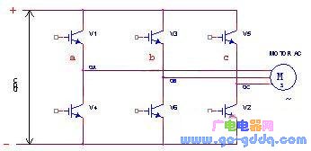
Figure 1-1 Voltage space vector and three-phase voltage type inverter circuit
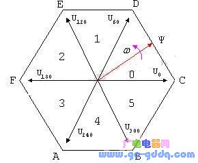
Figure 1-2 Regular hexagonal magnetic flux trajectory
Obviously, this power supply method can only form a regular hexagonal rotating magnetic field, rather than the circular rotating magnetic field we hope for.
How to obtain a circular rotating magnetic field? One idea is that if the rotating magnetic field formed in the stator is not a regular hexagon, but a regular polygon, we can get an approximate circular rotating magnetic field. Obviously, the more sides the regular polygon has, the greater the degree of approximation. However, there are only six non-zero basic voltage space vectors. If the phase obtains as many polygonal rotating magnetic fields as possible, there must be more inverter switching states. This linear time combination method is introduced below.

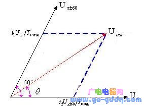
Figure 1-3 Linear combination of voltage space vectors
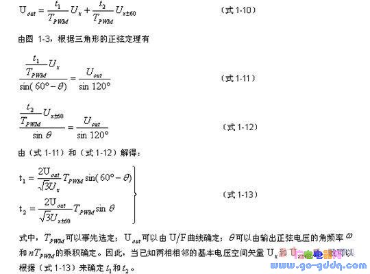
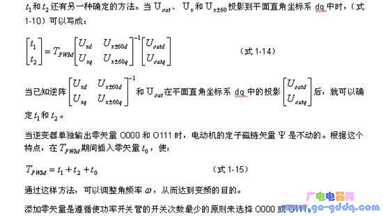
In order to make the movement speed of the magnetic flux smooth, the zero vector is generally not added in a concentrated manner, but the zero vector is evenly divided into several parts and inserted into the magnetic flux trajectory at multiple points, but the sum of the action time is still t0, which can reduce the pulsation of the motor torque.
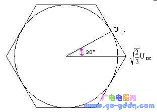
Figure 1-4 Maximum trajectory circle of Uout
Through the above synthesis method, the seven-segment voltage space vector PWM waveform shown in Figure 1-5 will eventually be obtained.
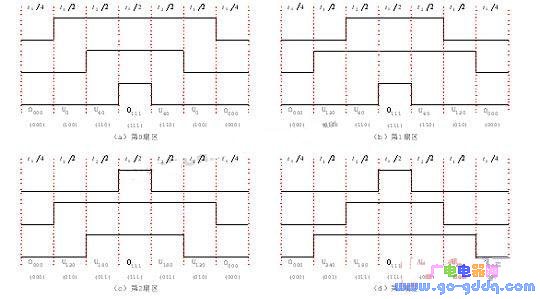

Figure 1-5 Seven-segment voltage space vector PWM waveform
1.4 Implementation of SVPWM on SPMC75
The MCP timer integrated in the SPMC75 series MCU can easily generate SVPWM. Figure 1-6 shows the block diagram of the SVPWM synthesis using SPMC75. The system includes PWM generation module, space vector conversion and other parts.
The PWM generator in the figure is implemented using the MCP timer of SPMC75. The MCP timer has multiple sets of comparison matching hardware inside. The system software only needs to send the calculated timing values required for the synthesis of the three SVPWMs into the corresponding comparison matching registers. The MCP can automatically output the required three-phase six-channel complementary SVPWM; at the same time, the MCP integrates dead zone insertion hardware and system protection logic to minimize the difficulty of user development.
The space vector conversion part mainly realizes the functions of vector conversion, sector calculation and vector time calculation. This part is implemented by software. The calculated time is directly sent to the PWM generator to output the required PWM waveform. The other parts in the block diagram are also implemented by software.
The u'nSP core used by SPMC75 has an integrated hardware multiplier and dedicated multiplication and accumulation instructions. It provides great help for the synthesis of the entire SVPWM. At a 24MHz system clock, it only takes 21us to implement the entire SVPWM synthesis algorithm.
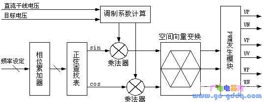
Figure 1-6 SVPWM synthesis block diagram
1.5 Conclusion
The newly launched SPMC75 by Sunplus Technology is a series of powerful industrial-grade MCUs with strong anti-interference capabilities. It integrates high-performance ADC, enhanced timer counter and other functional components. The powerful timer and PWM generation functions make it have outstanding performance in the field of motor control. The SPMC75 series MCU can easily form a high-performance drive system for various motors.
Previous article:Design and implementation of hardware and software for an embedded USB host system
Next article:VDK and embedded file system put into use
 Professor at Beihang University, dedicated to promoting microcontrollers and embedded systems for over 20 years.
- LED chemical incompatibility test to see which chemicals LEDs can be used with
- Application of ARM9 hardware coprocessor on WinCE embedded motherboard
- What are the key points for selecting rotor flowmeter?
- LM317 high power charger circuit
- A brief analysis of Embest's application and development of embedded medical devices
- Single-phase RC protection circuit
- stm32 PVD programmable voltage monitor
- Introduction and measurement of edge trigger and level trigger of 51 single chip microcomputer
- Improved design of Linux system software shell protection technology
- What to do if the ABB robot protection device stops
- Huawei's Strategic Department Director Gai Gang: The cumulative installed base of open source Euler operating system exceeds 10 million sets
- Download from the Internet--ARM Getting Started Notes
- Learn ARM development(22)
- Learn ARM development(21)
- Learn ARM development(20)
- Learn ARM development(19)
- Learn ARM development(14)
- Learn ARM development(15)
- Analysis of the application of several common contact parts in high-voltage connectors of new energy vehicles
- Wiring harness durability test and contact voltage drop test method
- Static Timing Analysis Basics and Applications
- How much do you know about the performance improvement of Wi-Fi 6 routers?
- What is the problem with amplifier instability?
- 【RPi PICO】Breathing light
- Why does the resolution decrease when the gain is increased?
- Evaluation of the domestic FPGA Gaoyun GW1N-4 series development board - Software Part 2
- A busbar power supply plant power rapid protection anti-sway cabinet
- How to put C2000 into low power mode
- GD32F350 is easy to use
- Industrial and Automation Solutions Collection

 Easy to play with STM32 microcontroller (Yang Baijun)


 京公网安备 11010802033920号