The serial port is the most frequently used problem in programming. It is usually used to send and receive data. At the same time, it has another function - to detect whether the program is correct. The STM32F030 series microcontroller naturally has a serial port. This article mainly introduces several commonly used simple applications of STM32F030_USART and its functional configuration.
1 Overview
The Universal Synchronous Asynchronous Receiver/Transmitter (USART) provides a flexible way for the MCU to communicate with external devices in full-duplex asynchronous serial data in the form of industrial standard NRZ. The USART can use a fractional baud rate generator to provide an ultra-wide baud rate setting range. DMA can be used to implement multi-buffer settings to support high-speed data communication.
Full-duplex, asynchronous communication
Configurable 16x or 8x oversampling method provides flexible choice between speed and clock tolerance
Fractional Baud Rate Generator
Automatic baud rate detection
Single-line half-duplex communication
The number of stop bits can be set - supports 1 or 2 stop bits
Fourteen interrupt sources and interrupt flags
- CTS toggle
- LIN break detect
- Transmit data register empty
- Transmit complete
- Receive data register full
- Line idle detected
- Overrun error
- Framing error
- Noise error
- Parity error
- Address/character match
- Receive timeout interrupt
- Block end interrupt
- Wake-up from Stop modeParity control:
- Send parity bit
- Receive parity check
2. Preparation
Read the STM32F030x data sheet carefully
Understand the operation principle of USART
View the STM32F030 development board schematics and package diagrams
The computer is equipped with keil and other compilation software
3. Register Description
Control Register 1 (USART_CR1) 


Control Register 2 (USART_CR2) 


Control Register 3 (USART_CR3) 


Baud Rate Register (USART_BRR) 
Guard Time and Prescaler Register (USART_GTPR) 
Interrupt and Status Register (USART_ISR) 


Interrupt Flag Clear Register (USART_ICR) 

Data Receive Register (USART_RDR) 
Data Transmit Register (USART_TDR) 
4. USART Configuration
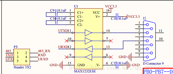
USART Schematic


USART code analysis①USART
initialization
void Usart_Init(uint32_t BaudRate)
{
    USART_InitTypeDef USART_InitStruct;
    GPIO_InitTypeDef GPIO_InitStruct;

    RCC_APB2PeriphClockCmd(RCC_APB2Periph_USART1,ENABLE);
    RCC_AHBPeriphClockCmd(RCC_AHBPeriph_GPIOA,ENABLE);

    /*
    PA9-TX-Push-Pull Multiplexing
    PA10-RX-Floating input/pull-up input
    */
    GPIO_PinAFConfig(GPIOA,GPIO_PinSource9,GPIO_AF_1);
    GPIO_PinAFConfig(GPIOA,GPIO_PinSource10,GPIO_AF_1);

    GPIO_InitStruct.GPIO_Pin=GPIO_Pin_9;
    GPIO_InitStruct.GPIO_Mode=GPIO_Mode_AF;
    GPIO_InitStruct.GPIO_OType=GPIO_OType_PP;
    GPIO_InitStruct.GPIO_Speed=GPIO_Speed_50MHz;
    GPIO_Init(GPIOA,&GPIO_InitStruct);

    GPIO_InitStruct.GPIO_Pin=GPIO_Pin_10;
    GPIO_InitStruct.GPIO_Mode=GPIO_Mode_AF;
    GPIO_InitStruct.GPIO_OType=GPIO_OType_PP;
    GPIO_InitStruct.GPIO_Speed=GPIO_Speed_50MHz;
    GPIO_InitStruct.GPIO_PuPd=GPIO_PuPd_UP;
    GPIO_Init(GPIOA,&GPIO_InitStruct);

    /*USART basic configuration*/
    USART_InitStruct.USART_BaudRate=BaudRate;
    USART_InitStruct.USART_HardwareFlowControl=USART_HardwareFlowControl_None;
    USART_InitStruct.USART_Mode=USART_Mode_Tx|USART_Mode_Rx;
    USART_InitStruct.USART_Parity=USART_Parity_No;
    USART_InitStruct.USART_StopBits=USART_StopBits_1;
    USART_InitStruct.USART_WordLength=USART_WordLength_8b;
    USART_Init(USART1,&USART_InitStruct);

    /*Enable receive interrupt*/
    NVIC_Config(USART1_IRQn);
    USART_ITConfig(USART1, USART_IT_RXNE, ENABLE);

    USART_Cmd(USART1,ENABLE);}12345678910111213141516171819202122232425262728293031323334353637383940414243
② USART sends data
void USART1_SendBuf(uint8_t *pBuf, uint32_t u32Len){    while(u32Len--)
    { /*Judge whether the send buffer is empty*/
        while(!USART_GetFlagStatus(USART1,USART_FLAG_TXE));        USART_SendData(USART1,*pBuf++);
    }
}123456789
③USART receives data
uint8_t USART1_ReceiverBuf(void){ /*Judge whether the receive buffer is not empty*/
    while(!USART_GetFlagStatus(USART1,USART_FLAG_RXNE));
    return USART_ReceiveData(USART1);
}123456
3. Remapping of printf function
int fputc(int ch, FILE *f)
{
    USART_SendData(USART1,(uint8_t)ch); while (!USART_GetFlagStatus(USART1, USART_FLAG_TXE)); return (ch);
}123456
5. Summary
When using the printf function of USART, be sure to open the micro library: click the magic wand symbol on the Keil toolbar, enter the Target configuration, and check Use MicroLib
Previous article:Redirection problem of printf and scanf in STM32
Next article:STM32F030_I2C detailed configuration instructions
- Popular Resources
- Popular amplifiers
- Learn ARM development(16)
- Learn ARM development(17)
- Learn ARM development(18)
- Embedded system debugging simulation tool
- A small question that has been bothering me recently has finally been solved~~
- Learn ARM development (1)
- Learn ARM development (2)
- Learn ARM development (4)
- Learn ARM development (6)
 Professor at Beihang University, dedicated to promoting microcontrollers and embedded systems for over 20 years.
- LED chemical incompatibility test to see which chemicals LEDs can be used with
- Application of ARM9 hardware coprocessor on WinCE embedded motherboard
- What are the key points for selecting rotor flowmeter?
- LM317 high power charger circuit
- A brief analysis of Embest's application and development of embedded medical devices
- Single-phase RC protection circuit
- stm32 PVD programmable voltage monitor
- Introduction and measurement of edge trigger and level trigger of 51 single chip microcomputer
- Improved design of Linux system software shell protection technology
- What to do if the ABB robot protection device stops
- Detailed explanation of intelligent car body perception system
- How to solve the problem that the servo drive is not enabled
- Why does the servo drive not power on?
- What point should I connect to when the servo is turned on?
- How to turn on the internal enable of Panasonic servo drive?
- What is the rigidity setting of Panasonic servo drive?
- How to change the inertia ratio of Panasonic servo drive
- What is the inertia ratio of the servo motor?
- Is it better for the motor to have a large or small moment of inertia?
- What is the difference between low inertia and high inertia of servo motors?
- Asynchronous Timing Design in ASIC.pdf
- [Repost] "Very Silly" Circuit Problem
- E840-DTU device connection to Alibaba Cloud test
- Interface corresponding to SNVS_TAMPER3 signal
- Looking for a good and available domestic accelerometer
- nRF52832-QFAA Hardware Reference Design
- 【RPi PICO】Snapshot of the RP2040 chip
- Why does TIM1_CH3N not output PWM after configuring PWM in STM32F103C8T6?
- Can you recommend a chip that can boost 3.3V to 5V?
- How to quickly gain points?


 NE532N


 京公网安备 11010802033920号