Start with the project for PWM output experiment and add various other functions.
LCD screen display:
1. Hardware 
, where timer generates pulses.
2. Hallib 
FMC is an interface that controls SDRAM and LCD.
3. #include
#include "lcd.h"#include "sdram.h"12
4. init()
SDRAM_Init(); //Initialize SDRAM
LCD_Init(); //LCD initialization

These two initializations are the key parts. First, SDRAM_Init(); is the underlying driver file of SDRAM. LCD_Init(); will call ltdc_init(), and HAL_SDRAM_Init() will also be used.
USMART Debugging:
1. Include the USMART folder and its path (not hardware, no hallib)
2. #include "usmart.h"
3. usmart_dev.init(108); // Initialize USMART
4. In usmart_config.c, include timer.h, and add TIM3_PWM_Init function where the function is added 
5. Open the serial port debugging assistant and directly send TIM3_PWM_Init(999,107). At the same time, you can change the rotation angle of the servo at any time. 
RTC clock:
1.hardware
rtc folder
2.hallib
stm32f7xx_hal_rtc.c
stm32f7xx_hal_rtc_ex.c
3.include
rtc.h
4.main
RTC_TimeTypeDef RTC_TimeStruct;
    RTC_DateTypeDef RTC_DateStruct;
    u8 tbuf[40];
    u8 t=0;
RTC_Init(); //Initialize RTC
t++; if((t%10)==0) //Update the displayed data every 100ms
        {
            HAL_RTC_GetTime(&RTC_Handler,&RTC_TimeStruct,RTC_FORMAT_BIN);            sprintf((char*)tbuf,"Time:%02d:%02d:%02d",RTC_TimeStruct.Hours,RTC_TimeStruct.Minutes,RTC_TimeStruct.Seconds);
            LCD_ShowString(30,140,210,16,16,tbuf);
            HAL_RTC_GetDate(&RTC_Handler,&RTC_DateStruct,RTC_FORMAT_BIN);            sprintf((char*)tbuf,"Date:20%02d-%02d-%02d",RTC_DateStruct.Year,RTC_DateStruct.Month,RTC_DateStruct.Date);
            LCD_ShowString(30,160,210,16,16,tbuf);
            sprintf((char*)tbuf,"Week:%d",RTC_DateStruct.WeekDay);
            LCD_ShowString(30,180,210,16,16,tbuf);
        }1234567891011121314151617
5.usmart 6.interrupt processing callback function 
in rtc.c :
#include "timer.h" //RTC alarm A interrupt processing callback function void HAL_RTC_AlarmAEventCallback(RTC_HandleTypeDef *hrtc)
{
    printf("ALARM A!\r\n");
    TIM3_PWM_Init(1000*-1,108-1);
}1234567
Wake up from standby:
1.hardware
wkup
2.hallib
无
3.include
#include "wkup.h"1
4.main
WKUP_Init(); //Standby wakeup initialization
LCD_Init(); //Initialize LCD
LCD_Init must be after WKUP_Init. Each click of a button will enter the main function, and will enter WKUP_Init():
//WKUP_Heat:
    if(Check_WKUP()==0)
    { Sys_Enter_Standby(); //Not booting up, entering standby mode
    }//Key interrupt:
    if(Check_WKUP())//Shutdown
        { Sys_Enter_Standby(); //Enter standby mode
        }1234567891011
If the key is pressed for less than 3 seconds, it will directly enter standby mode by calling Check_WKUP()==0; if it is pressed for 3 seconds, it will skip Sys_Enter_Standby() and boot normally, and turn on the key interrupt. If the key is pressed for less than 3 seconds after booting, it will enter interrupt judgment and will not enter Sys_Enter_Standby(); if it is pressed for 3 seconds after booting, it will directly enter standby mode.
TPAD:
1.hardware
tpad
2.hallib
无
3.include
#include "tpad.h"1
4.main
TPAD_Init(8); //Initialize the touch button, counting at 108/8=13.5Mhz frequency
 switch (TPAD_Scan(0)) //Successfully captured a rising edge (this function execution time is at least 15ms)
        {            case 0:
                LCD_LED(1); //Turn on the backlight
                LED1(1);                break;            case 1:
                LCD_LED(0); //Turn off the backlight
                LED1(0);                break;
        }switch (TPAD_Scan(0)) loops inside while(1). 12345678910111213
5.tpad.c
u8 TPAD_Scan(u8 mode)
{ static u8 keyen=0; //0, can start detection;>0, can not start detection
    static u8 res=0; u8 sample=3; //The default sampling frequency is 3 times
    u16 rval;    if(mode)
    {
        sample=6; //When continuous pressing is supported, set the sampling frequency to 6 times
        keyen=0; //Support continuous pressing
    }
    rval=TPAD_Get_MaxVal(sample);
    if(rval>(tpad_default_val*4/3)&&rval<(10*tpad_default_val))//greater than tpad_default_val+TPAD_GATE_VAL, and less than 10 times tpad_default_val, then it is valid
    {
        if(keyen==0)res++; //greater than tpad_default_val+TPAD_GATE_VAL, yes
        //printf("r:%d\r\n",rval);
        keyen=3; //The key will be effective after at least 3 more times
    }
    if(keyen)keyen--;
    res=res%2;    return res;
}

First, the default is channel 1 of time2, and the gpio is pa5. However, pa5 will conflict with the subsequent ADC, so select channel 3 of time2, and the gpio is pa2.
Just change GPIO_PIN_2 and TIM_CHANNEL_3, and ignore GPIO_AF1_TIM2. 12345678910111213141516171819202122232425
ADC:
1.hardware
ADC
2.hallib
adc.c以及adc_ex.c
3.main
#include“adc.h”u16 adcx;float temp;
MY_ADC_Init(); //Initialize ADC1 channel adcx=Get_Adc_Average(ADC_CHANNEL_5,20); //Get the conversion value of channel 5, average 20 times
        LCD_ShowxNum(134,130,adcx,4,16,0); //Display the original value after ADCC sampling
        temp=(float)adcx*(3.3/4096); //Get the actual voltage value with decimal after calculation, such as 3.1111
        adcx=temp; //Assign the integer part to the adcx variable, because adcx is a u16 integer
        LCD_ShowxNum(134,150,adcx,1,16,0); //Display the integer part of the voltage value. For example, 3.1111 will be displayed as 3.
        temp-=adcx; //Remove the integer part that has been displayed and leave the decimal part, such as 3.1111-3=0.1111
        temp*=1000; //Multiply the decimal part by 1000. For example, 0.1111 is converted to 111.1, which is equivalent to retaining three decimal places.
        LCD_ShowxNum(150,150,temp,3,16,0X80); //Display the decimal part (converted to integer display before), here it shows 111.1234567891011
When the internal temperature sensor is short temp.
4. Driver file
ADC1_Handler.Init.Resolution=ADC_RESOLUTION_12B;             //12位模式GPIO_InitTypeDef GPIO_Initure;
    __HAL_RCC_ADC1_CLK_ENABLE(); //Enable ADC1 clock
    __HAL_RCC_GPIOA_CLK_ENABLE(); //Enable GPIOA clock

    GPIO_Initure.Pin=GPIO_PIN_5;            //PA5
    GPIO_Initure.Mode=GPIO_MODE_ANALOG;     //模拟
    GPIO_Initure.Pull=GPIO_NOPULL; //Without pull-up and pull-down
    HAL_GPIO_Init(GPIOA,&GPIO_Initure);12345678910
Get_Adc_Average(ADC_CHANNEL_5,20) is to get the value of channel 5, so PA5 needs to be initialized. If it is an internal temperature sensor, it is connected to channel 18, and PA5 is ignored. In HAL_ADC_MspInit, only the ADC1 clock needs to be enabled. The Get_Temprate function will get the voltage value of channel 18, temperate=(float)adcx*(3.3/4096); the default reference voltage is 0-3.3V, and the resolution is 12 bits. What is obtained in the channel is digital, and the corresponding voltage can be obtained after conversion.
DAC:
1.hardware
DAC
2.hallib
dac.c and dac_ex.c
3.main
#include "dac.h"u16 dacval=0;u8 key;
DAC1_Init(); //Initialize DAC1LCD_ShowString(30,150,200,16,16,"DAC VAL:");
    LCD_ShowString(30,170,200,16,16,"DAC VOL:0.000V");
    LCD_ShowString(30,190,200,16,16,"ADC VOL:0.000V");
key=KEY_Scan(0);
        if(key==KEY2_PRES)
        {
            if(dacval<4000)dacval+=200;
            HAL_DAC_SetValue(&DAC1_Handler,DAC_CHANNEL_1,DAC_ALIGN_12B_R,dacval); //Set DAC value
        }else if(key==KEY1_PRES)
        {            if(dacval>200)dacval-=200;            else dacval=0;
            HAL_DAC_SetValue(&DAC1_Handler,DAC_CHANNEL_1,DAC_ALIGN_12B_R,dacval); //Set DAC value
        }
        if(t==10||key==KEY1_PRES||key==KEY2_PRES) //WKUP/KEY1 is pressed, or the timer is up
        {
            adcx=HAL_DAC_GetValue(&DAC1_Handler,DAC_CHANNEL_1); //Read the previously set DAC value
            LCD_ShowxNum(94,150,adcx,4,16,0); //Display DAC register value
            temp=(float)adcx*(3.3/4096); //Get DAC voltage value
            adcx=temp;
            LCD_ShowxNum(94,170,temp,1,16,0); //Display the integer part of the voltage value
            temp-=adcx;
            temp*=1000;
            LCD_ShowxNum(110,170,temp,3,16,0X80); //Display the decimal part of the voltage value
            adcx=Get_Adc_Average(ADC_CHANNEL_5,10); //Get ADC conversion value
            temp=(float)adcx*(3.3/4096); //Get ADC voltage value
            adcx=temp;
            LCD_ShowxNum(94,190,temp,1,16,0); //Display the integer part of the voltage value
            temp-=adcx;
            temp*=1000;
            LCD_ShowxNum(110,190,temp,3,16,0X80); //Display the decimal part of the voltage value
            t=0;
        }
        delay_ms(10);12345678910111213141516171819202122232425262728293031323334353637
4. Driver file
PA4 is used as the output channel of DAC. First, use the key control to give it a number. This number is put into the DAC channel. The signal put into the DAC channel is a digital signal. Then read the value of the DAC channel, which is a number. Convert the number into the corresponding analog voltage (0-3300 corresponds to 0-3.3V). At this time, you can read the value of channel 1 and convert it into an analog voltage.
PA4 and PA5 are connected with jumper caps. PA5 is used as the input channel of ADC. The signal put into the ADC channel is an analog signal. Then the value of the channel read is an analog number, which is converted into the corresponding digital voltage (0-3300 corresponds to 0-3.3V). After further conversion, a digital voltage value is obtained.
pcf8574:
PCF8574 is an IO port expansion chip. 2 IO ports can expand up to 64 IO ports.
1. Hardware
IIC and PCF8574
2. Halib
no
3. Main
#include "pcf8574.h"u8 beepsta=1; //pcf8574PCF8574_Init(); //Initialize PCF8574if(key==KEY0_PRES)//KEY0 is pressed, read the string and display it
        {
            beepsta=!beepsta; //Invert the buzzer status
            PCF8574_WriteBit(BEEP_IO,beepsta); //control the buzzer
        } if(PCF8574_INT==0) //PCF8574 interrupt low level is valid
        {
            key=PCF8574_ReadBit(EX_IO); //Read the EXIO status and clear the interrupt output of PCF8574 (INT returns to high level)
            if(key==0)LED0_Toggle; //LED1 status inverted
        }

PCF8574_INT is judged for time-sharing multiplexing. If EX_IO is repeatedly touched with a low level, the interrupt of PCF8574 will be triggered. 123456789101112131415
4. Driver files
IIC_Init();
At the same time, initialize PB12 (INT pin of PCF8574 is connected to PB12 of stm32f767) as pull-up input;
Set all io to high level. 123
touchscreen:
1.hardware
24CXX and touch
2.hallib
no
3.main
#include "touch.h"u8 t1=0;u16 lastpos[5][2]; //touch screen
tp_dev.init(); //Touch screen initialization
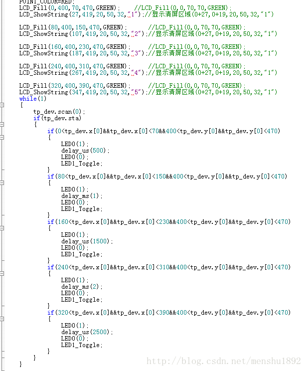
tp_dev.scan(0); if(tp_dev.sta) { if(tp_dev.x[t1]It means that there is no need for 5-point touch, and it will respond immediately when touched. If you want to draw a button to control the rotation of the servo, you can refer to the following figure:

4. Driver file
The 5-point touch judgment is also removed in u8 FT5206_Scan (u8 mode).
Infrared remote control:
1.hardware
remote
2.hallib
无
3.main
#include "remote.h" Remote_Init(); //Initialize infrared reception key=Remote_Scan();
if(key)
{
LCD_ShowNum(86,130,key,3,16); //Display key value
LCD_ShowNum(86,150,RmtCnt,3,16); //Show the number of key presses
switch(key)
{ case 0:str="ERROR";break;
case 162:str="POWER";break;
case 98:str="UP";break;
case 2:str="PLAY";break;
case 226:str="ALIENTEK";break;
case 194:str="RIGHT";break;
case 34:str="LEFT";break;
case 224:str="VOL-";break;
case 168:str="DOWN";break;
case 144:str="VOL+";break;
case 104:str="1";TIM3_PWM_Init(1000-1,108-1);break;
case 152:str="2";TIM3_PWM_Init(2000-1,108-1);break;
case 176:str="3";TIM3_PWM_Init(3000-1,108-1);break;
case 48:str="4";TIM3_PWM_Init(4000-1,108-1);break;
case 24:str="5";TIM3_PWM_Init(5000-1,108-1);break;
case 122:str="6";break;
case 16:str="7";break;
case 56:str="8";break;
case 90:str="9";break; case 66:str="0";break; case 82:str="DELETE";break;
}
}else delay_ms(10);
LCD_Fill(86,170,86+8*8,170+16,WHITE); //Clear previous display
LCD_ShowString(86,170,200,16,16,str); //Show SYMBOL12345678910111213141516171819202122232425262728293031323334Note that you must judge if(key) here, otherwise the interface will be refreshed crazily.
4. Driver file
infrared remote control is also input capture, using channel 1 of timer 1, so it does not conflict with pwm timer 3.

FLASH:
1.hardware
STMFLASH
2.hallib
flash/flash.ex
3.main
#include "stmflash.h" // string array to be written to STM32 FLASH const u8 TEXT_Buffer[] = {"STM32 FLASH TEST"}; #define TEXT_LENTH sizeof(TEXT_Buffer) // array length #define SIZE TEXT_LENTH/4+((TEXT_LENTH%4)?1:0) #define FLASH_SAVE_ADDR 0X08020000 // set FLASH save address (must be a multiple of 4, and the sector must be larger than the sector occupied by this code.
//Otherwise, the entire sector may be erased during the write operation, causing part of the program to be lost and causing a crash. u8 datatemp[SIZE];
LCD_ShowString(30,170,200,16,16,"Start Write FLASH....");
STMFLASH_Write(FLASH_SAVE_ADDR,(u32*)TEXT_Buffer,SIZE);
LCD_ShowString(30,170,200,16,16,"FLASH Write Finished!");//Prompt that the transfer is completed STMFLASH_Read(FLASH_SAVE_ADDR,(u32*)datatemp,SIZE);
LCD_ShowString(30,170,200,16,16,"The Data Readed Is: ");//Prompt that the transmission is completed
LCD_ShowString(30,190,200,16,16,datatemp);//Display the read string 1234567891011121314151617FLASH:
1.hardware
STMFLASH
2.hallib
flash/flash.ex
3.main
Previous article:stm32 controls mpu9250 nine-axis sensor
Next article:stm32 controls the rotation of the servo DS3115
- Popular Resources
- Popular amplifiers
 Professor at Beihang University, dedicated to promoting microcontrollers and embedded systems for over 20 years.
- LED chemical incompatibility test to see which chemicals LEDs can be used with
- Application of ARM9 hardware coprocessor on WinCE embedded motherboard
- What are the key points for selecting rotor flowmeter?
- LM317 high power charger circuit
- A brief analysis of Embest's application and development of embedded medical devices
- Single-phase RC protection circuit
- stm32 PVD programmable voltage monitor
- Introduction and measurement of edge trigger and level trigger of 51 single chip microcomputer
- Improved design of Linux system software shell protection technology
- What to do if the ABB robot protection device stops
- Keysight Technologies Helps Samsung Electronics Successfully Validate FiRa® 2.0 Safe Distance Measurement Test Case
- Innovation is not limited to Meizhi, Welling will appear at the 2024 China Home Appliance Technology Conference
- Innovation is not limited to Meizhi, Welling will appear at the 2024 China Home Appliance Technology Conference
- Huawei's Strategic Department Director Gai Gang: The cumulative installed base of open source Euler operating system exceeds 10 million sets
- Download from the Internet--ARM Getting Started Notes
- Learn ARM development(22)
- Learn ARM development(21)
- Learn ARM development(20)
- Learn ARM development(19)
- Learn ARM development(14)
- [NUCLEO-L552ZE Review] Unboxing and Onboard Resource Analysis
- GD32L233C-START Evaluation——02_2. Build development environment and simple debugging
- [Zhongke Bluexun AB32VG1 RISC-V board "encounter" RTT evaluation] 1: Fill the pit and run the first light-up program
- IAR platform transplants TI OSAL to STC8A8K64S4A12 MCU
- [Xianji HPM6750 Review] PWM Control Buzzer Sound
- Interface ov5640_camera
- EEWORLD University Hall----Engineering is smarter, industrial design is more powerful-field transmitter and smart meter design solution
- Startup interface kernel code modification
- DC regulated power supply to charge the battery
- The most comprehensive Fudan Micro MCU chip selection information on the entire network


 MAX916ESE+


 京公网安备 11010802033920号