A quadcopter is an aircraft that uses four rotors as flight engines to fly in the air. Since the 20th century, the rapid development of electronic technology has led to the miniaturization of quadcopters, and the integration of artificial intelligence has led to the development of drones and intelligent robots.

The quadcopter not only achieves the vertical take-off and landing flight performance of a helicopter, but also reduces the design difficulty of the aircraft's mechanical structure to a certain extent. The balance control system of the quadcopter is composed of various inertial sensors. During the production process, the requirements for the center, symmetry and motor performance of the overall fuselage are relatively low, which is also the advantage of making a quadcopter. Compared with fixed-wing aircraft, the quadcopter also has the advantages of vertical take-off and landing, good maneuverability, and easy maintenance.
System solutions
This design uses STM32F4 as the core processor. The processor core architecture is ARM Cortex-M4, which has the characteristics of high performance, low cost and low power consumption.

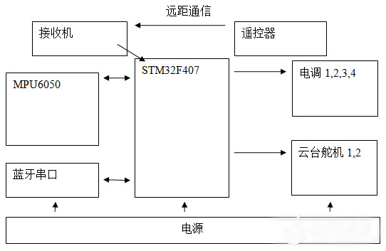
Design overall block diagram
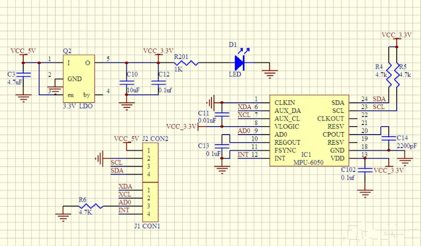
The main control board includes the sensor MPU6050 circuit module, wireless Bluetooth module, motor start module, power management module, etc. The remote control uses a commercial remote control and receiver. The control chip captures the PPM command signal of the receiver, the sensor and the control chip are connected by IIC bus, and the MCU and the ESC transmit the control signal by PWM.

MPU-6050 circuit schematic
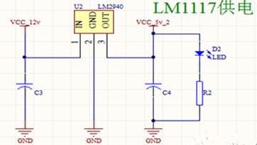
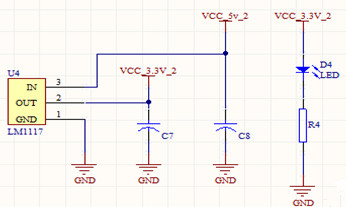
Power Management Module
The quadcopter requires a light overall design and a small size. Therefore, in terms of battery selection, a small, light, and large-capacity lithium battery is the most suitable. The core chip of the system is STM32F103, and the common operating voltage is 3.3V. At the same time, the conventional power supply voltage of the inertial measurement sensor and Bluetooth communication module is also 3.3V. The voltage of the lithium battery is 11.4V. To make the system work properly, the 11.4V lithium battery voltage needs to be stabilized to 3.3V. The commonly used 78 series voltage regulator chip is no longer applicable, and a voltage regulator chip with better performance must be selected.

After comprehensive consideration, this circuit uses the core chips of LM1117-3.3 and LM2940-5 power supply. The battery power is reduced to 5V by LM2940-5 and then input to LM1117-3.3 to stabilize the voltage to 3.3V. Since the current of the motor part is large, overcurrent protection is added to the flight control circuit part, and a 500mA fuse is used.


Editor's Notes
This design is a four-axis aerial photography platform based on STM32F4. With STM32F407 as the control core, the four-axis aircraft as the carrier, and the aerial photography system supplemented by the gimbal. The hardware consists of flight control circuits, power management and other systems. It has the characteristics of flexibility, lightness, ductility, and good adaptability. In practical applications, the four-axis aircraft can complete specific flight missions in complex and dangerous environments, and can also be used to monitor traffic and environment.
Previous article:The difference between main() and __main() in ARM
Next article:MCU-controlled battery management enables successful Internet
- Popular Resources
- Popular amplifiers
- Learn ARM development(16)
- Learn ARM development(17)
- Learn ARM development(18)
- Embedded system debugging simulation tool
- A small question that has been bothering me recently has finally been solved~~
- Learn ARM development (1)
- Learn ARM development (2)
- Learn ARM development (4)
- Learn ARM development (6)
 Professor at Beihang University, dedicated to promoting microcontrollers and embedded systems for over 20 years.
- LED chemical incompatibility test to see which chemicals LEDs can be used with
- Application of ARM9 hardware coprocessor on WinCE embedded motherboard
- What are the key points for selecting rotor flowmeter?
- LM317 high power charger circuit
- A brief analysis of Embest's application and development of embedded medical devices
- Single-phase RC protection circuit
- stm32 PVD programmable voltage monitor
- Introduction and measurement of edge trigger and level trigger of 51 single chip microcomputer
- Improved design of Linux system software shell protection technology
- What to do if the ABB robot protection device stops
- Detailed explanation of intelligent car body perception system
- How to solve the problem that the servo drive is not enabled
- Why does the servo drive not power on?
- What point should I connect to when the servo is turned on?
- How to turn on the internal enable of Panasonic servo drive?
- What is the rigidity setting of Panasonic servo drive?
- How to change the inertia ratio of Panasonic servo drive
- What is the inertia ratio of the servo motor?
- Is it better for the motor to have a large or small moment of inertia?
- What is the difference between low inertia and high inertia of servo motors?
- MSP430 communication resources IIC communication
- [Seeking guidance] RSL10 small light does not flash
- The weekly review information is here~ New activities will be launched this week
- How to use 3.3V of stm32 to control 5V servo?
- Transformation of 4-20mA two-wire passive digital display meter, Part 8 (Optical coupler experiment)
- Book a live broadcast and get a gift: Verify the 5G core network to ensure optimal performance (4G changes life, what can 5G change?)
- Help: I wrote a program using DS18B20 but I don’t know why it only displays 85 degrees Celsius. Please help me figure out what to do.
- How to flip and restore the PCB in Altium Designer 19 in 3D
- [STM32WB55 Review] 6# Use of STM32WB development board UART
- [New Year's Taste Competition] + New Year's Eve dinner + New Year's 7 days of fun, I wish you all a prosperous New Year, smooth sailing and a good start.

 HA3-2405-5


 京公网安备 11010802033920号