1. The experimental task
is to move a single light left and right. The hardware circuit is shown in Figure 4.4.1. The eight light-emitting diodes L1-L8 are connected to the P1.0-P1.7 interfaces of the single-chip computer. When the output is "0", the light-emitting diodes light up. At the beginning, P1.0→P1.1→P1.2→P1.3→┅→P1.7→P1.6→┅→P1.0 lights up, and the cycle repeats.
2. Circuit schematic diagram

Figure 4.4.1
3. Hardware connection on the system board
Connect P1.0-P1.7 in the "single-chip system" area to the L1-L8 port in the "eight-way LED indicator module" area with an 8-core cable. The requirements are: P1.0 corresponds to L1, P1.1 corresponds to L2, ..., P1.7 corresponds to L8.
4. Program design content
We can use the output port instruction MOV P1, A or MOV P1, #DATA. As long as the accumulator value or constant value is given, and then the above instruction is executed, the output control action can be achieved.
The data sent each time is different. The specific data is shown in Table 1 below
P1.7
P1.6
P1.5
P1.4
P1.3
P1.2
P1.1
P1.0
illustrate
L8
L7
L6
L5
L4
L3
L2
L1
1
1
1
1
1
1
1
0
L1 Bright
1
1
1
1
1
1
0
1
L2 Bright
1
1
1
1
1
0
1
1
L3 Bright
1
1
1
1
0
1
1
1
L4 Bright
1
1
1
0
1
1
1
1
L5 Bright
1
1
0
1
1
1
1
1
L6 Bright
1
0
1
1
1
1
1
1
L7 Bright
0
1
1
1
1
1
1
1
L8 Bright
Table 1
5. 
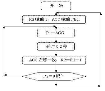
Flowchart
Figure 4.4.2
6. Assembly source program
ORG 0
START: MOV R2,#8
MOV A,#0FEH
SETB C
LOOP: MOV P1,A
LCALL DELAY
RLC A
DJNZ R2,LOOP
MOV R2,#8
LOOP1: MOV P1,A
LCALL DELAY
RRC A
DJNZ R2 ,LOOP1
LJMP START
DELAY: MOV R5,#20;
D1: MOV R6,#20
D2: MOV R7,#248
DJNZ R7,$
DJNZ R6,D2
DJNZ R5,D1
RET
END
7. C language source program
#include
unsigned char i;
unsigned char temp;
unsigned char a,b;
void delay(void)
{
unsigned char m,n,s;
for(m=20;m>0;m --)
for(n=20;n>0;n--)
for(s=248;s>0;s--);
}
void main(void)
{
while(1)
{
temp=0xfe;
P1= temp;
delay();
for(i=1;i<8;i++)
{
a=temp<
P1=a|b;
delay();
}
for( i=1;i<8;i++)
{
a=temp>>i;
b=temp<<(8-i);
P1=a|b;
delay();
}
}
}
Reference address:4. Move the advertising light left and right
is to move a single light left and right. The hardware circuit is shown in Figure 4.4.1. The eight light-emitting diodes L1-L8 are connected to the P1.0-P1.7 interfaces of the single-chip computer. When the output is "0", the light-emitting diodes light up. At the beginning, P1.0→P1.1→P1.2→P1.3→┅→P1.7→P1.6→┅→P1.0 lights up, and the cycle repeats.
2. Circuit schematic diagram

Connect P1.0-P1.7 in the "single-chip system" area to the L1-L8 port in the "eight-way LED indicator module" area with an 8-core cable. The requirements are: P1.0 corresponds to L1, P1.1 corresponds to L2, ..., P1.7 corresponds to L8.
4. Program design content
We can use the output port instruction MOV P1, A or MOV P1, #DATA. As long as the accumulator value or constant value is given, and then the above instruction is executed, the output control action can be achieved.
The data sent each time is different. The specific data is shown in Table 1 below

ORG 0
START: MOV R2,#8
MOV A,#0FEH
SETB C
LOOP: MOV P1,A
LCALL DELAY
RLC A
DJNZ R2,LOOP
MOV R2,#8
LOOP1: MOV P1,A
LCALL DELAY
RRC A
DJNZ R2 ,LOOP1
LJMP START
DELAY: MOV R5,#20;
D1: MOV R6,#20
D2: MOV R7,#248
DJNZ R7,$
DJNZ R6,D2
DJNZ R5,D1
RET
END
7. C language source program
#include
unsigned char i;
unsigned char temp;
unsigned char a,b;
void delay(void)
{
unsigned char m,n,s;
for(m=20;m>0;m --)
for(n=20;n>0;n--)
for(s=248;s>0;s--);
}
void main(void)
{
while(1)
{
temp=0xfe;
P1= temp;
delay();
for(i=1;i<8;i++)
{
a=temp<
P1=a|b;
delay();
}
for( i=1;i<8;i++)
{
a=temp>>i;
b=temp<<(8-i);
P1=a|b;
delay();
}
}
}
Previous article:3. Multi-way switch status indication
Next article:1. Flashing lights
- Popular Resources
- Popular amplifiers
Recommended Content
Latest Microcontroller Articles
He Limin Column
Microcontroller and Embedded Systems Bible
 Professor at Beihang University, dedicated to promoting microcontrollers and embedded systems for over 20 years.
MoreSelected Circuit Diagrams
MorePopular Articles
- LED chemical incompatibility test to see which chemicals LEDs can be used with
- Application of ARM9 hardware coprocessor on WinCE embedded motherboard
- What are the key points for selecting rotor flowmeter?
- LM317 high power charger circuit
- A brief analysis of Embest's application and development of embedded medical devices
- Single-phase RC protection circuit
- stm32 PVD programmable voltage monitor
- Introduction and measurement of edge trigger and level trigger of 51 single chip microcomputer
- Improved design of Linux system software shell protection technology
- What to do if the ABB robot protection device stops
MoreDaily News
- Huawei's Strategic Department Director Gai Gang: The cumulative installed base of open source Euler operating system exceeds 10 million sets
- Download from the Internet--ARM Getting Started Notes
- Learn ARM development(22)
- Learn ARM development(21)
- Learn ARM development(20)
- Learn ARM development(19)
- Learn ARM development(14)
- Learn ARM development(15)
- Analysis of the application of several common contact parts in high-voltage connectors of new energy vehicles
- Wiring harness durability test and contact voltage drop test method
Guess you like
- Decomposition
- Serial communication between CC2541 and MSP430
- c6678 sys/bios add hwi interrupt does not trigger, send successfully in bare metal case
- NUCLEO_G431RB review->File structure & ST-Link online debugging experience
- Sugar Glider ⑤ Sugar Glider Health Monitoring System Based on RSL10--Project Introduction
- Problems with using the bq28z610EVM development board
- How to create a transcoding table using HZK16 font in micropython?
- 【TI recommended course】#What is I2C design tool? #
- Digital Input Closed-Loop Class-D Audio Amplifier Evaluation Module
- Come and recommend a book!!! April is a great time to read when the flowers are blooming and the grass is green!

 LTC6268HS6-10#PBF


 京公网安备 11010802033920号